Self-defoaming electric cooker

A rice cooker and defoaming technology, which is applied in the directions of preventing overflow, cooking utensils, household utensils, etc., can solve the problems of liquid overflow, residual bubbles, poor foam breaking effect of convex ribs, etc., and achieves the effect of improving efficiency and reducing waste.

Inactive Publication Date: 2020-07-10
于国飞
View PDF12 Cites 0 Cited by
  • Summary
  • Abstract
  • Description
  • Claims
  • Application Information

AI Technical Summary

Problems solved by technology

[0003] During the use of the rice cooker, a large number of air bubbles are often generated, which is easy to cause the liquid to overflow during cooking or soup. Usually, the ribs in the steam valve on the lid will break the bubbles, but the bubble breaking of the ribs The effect is poor, it can only eliminate a small part of the bubbles, and there are still a large number of bubbles left, which will easily cause the liquid in the rice cooker to flow out, which will bring great inconvenience to people's cooking or soup. Therefore, we propose self-defoaming Rice cooker to solve the above problems

Method used


Image

  • Self-defoaming electric cooker
  • Self-defoaming electric cooker
  • Self-defoaming electric cooker

Examples


Embodiment 1

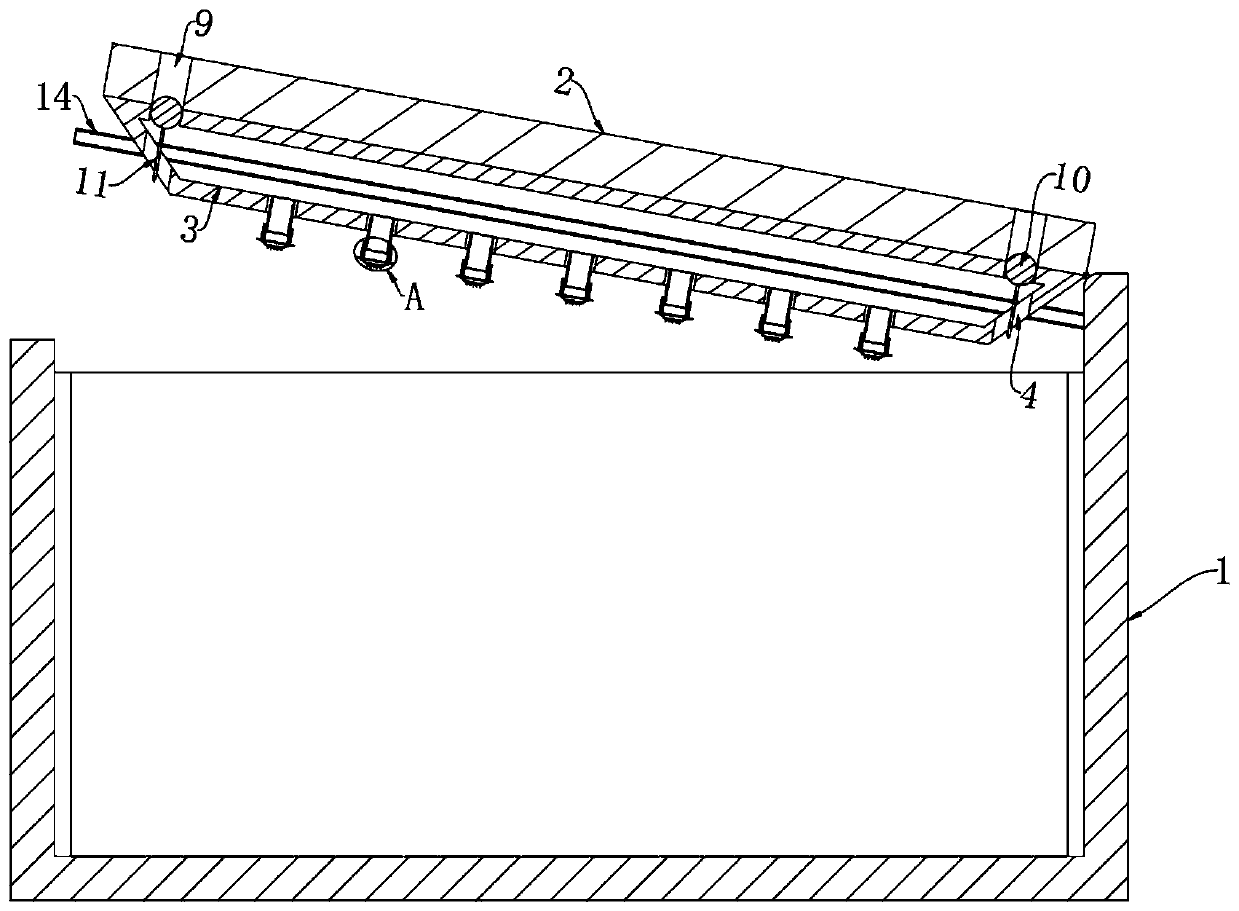
[0023] Such as Figure 1-2 As shown above, the self-defoaming rice cooker includes a rice cooker body 1, a cover plate 2 is arranged on the rice cooker body 1, and two second through holes 9 opposite to the first through holes 4 are opened on the cover plate 2. Hole 9 is provided with airtight ball 10, the lower end opening diameter of the second through hole 9 is slightly smaller than the diameter of airtight ball 10, the width of the upper end opening of the second through hole 9 is slightly less than the diameter of airtight ball 10, and the length of upper end opening is greater than The diameter of the airtight ball 10 and the structural design of the second through hole 9 can ensure that the air pressure is too high, and the airtight ball 10 will not be pushed out of the second through hole 9 when the airtight ball 10 is pushed up, and the airtight ball 10 can rise. During the process, a gap is formed in the second through hole 9 to facilitate pressure relief. When the s...

Embodiment 2

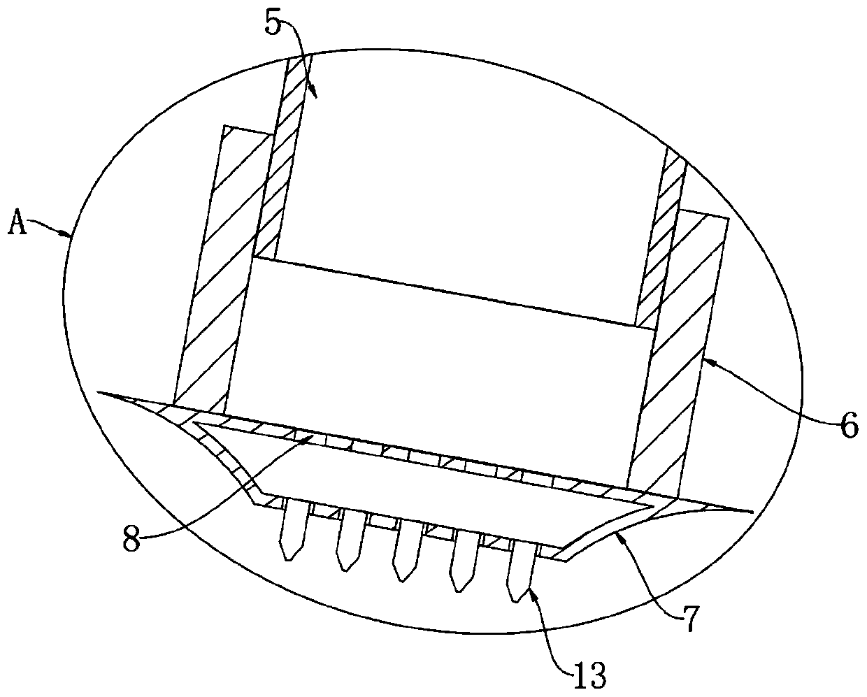
[0026] Such as Figure 3-4 As shown, the difference between this embodiment and Embodiment 1 is that the hollow tube 6 is sleeved on the communicating tube 5, and the hollow tube 6 is slidably connected with the communicating tube 5, and the baffle plate 7 and the communicating tube 5 are fixedly connected with a A plurality of return springs 12, when the steam acts on the baffle 7 through the connecting pipe 5, the baffle 7 will slide down through the hollow tube 6, and pull the return spring 12 at the same time, while the baffle 7 is sliding down, the needle-shaped tube 13 can be used to Structural features, puncture the air bubbles in the attachment, when the airtight ball 10 rises, when the pressure is released, the force of the steam weakens, and the baffle 7 will slide up the baffle 7 under the reaction force of the return spring 12, due to the return spring 12, the baffle 7 will vibrate up and down to a certain extent after returning to its position, and then drive the ...


PUM


Abstract

The invention belongs to the field of electric cookers, in particular to a self-defoaming electric cooker. The electric cooker comprises an electric cooker body, wherein a cover plate is arranged on the electric cooker body; the side wall of the lower end of the cover plate is fixedly connected with a hollow plate matched with the cover plate; two first through holes which are symmetrically formedare formed in the hollow plate; the hollow plate is communicated with a plurality of communicating pipes; the communicating pipes are communicated with a hollow pipe, the lower end of the hollow pipeis communicated with a baffle plate, the baffle plate is of a hollow structure, the side walls of the two sides of the baffle plate are both of an arc design, the side walls of the upper end and thelower end of the baffle plate are provided with a plurality of through vent holes, and the vent hole in the side wall of the lower end is communicated with a needle-shaped pipe. According to the electric cooker, impact airflow can be generated through steam backflow in the electric cooker, bubbles in the cooker are effectively eliminated, meanwhile, food in the cooker can be secondarily heated, and energy waste is reduced.

Description

technical field [0001] The invention belongs to the field of electric rice cookers, in particular to a self-defoaming electric rice cooker. Background technique [0002] Electric rice cooker is also called electric cooker, electric rice cooker. It is a cooker that converts electric energy into heat energy. It has various heating functions such as steaming, boiling, stewing, stewing, and simmering food. It is easy to use, safe and reliable. It can not only cook food, but also keep it warm. It is clean and hygienic to use, without pollution, saving time and effort. It is one of the indispensable tools for the modernization of housework. [0003] During the use of the rice cooker, a large number of air bubbles are often generated, which is easy to cause the liquid to overflow during the process of cooking rice or soup. Usually, the ribs in the steam valve on the lid will break the bubbles, but the bubble breaking of the ribs The effect is poor, it can only eliminate a small p...

Claims


Application Information

Patent Timeline
Patent Type & Authority Applications(China)
IPC IPC(8): A47J27/56A47J36/38
CPCA47J27/56A47J36/38
Inventor 于国飞黄宁宁
Owner 于国飞
Why Eureka
Try Eureka