
Solar panel support structure based on rotating centrifugal force

A technology of solar panels and rotating centrifugal force, applied in the field of solar photovoltaics, can solve the problems of inability to reduce damage to the back of solar panels, high working intensity, and low efficiency

Active Publication Date: 2020-07-07
厦门科惟智能制造有限公司
View PDF4 Cites 6 Cited by
  • Summary
  • Abstract
  • Description
  • Claims
  • Application Information

AI Technical Summary

Problems solved by technology

[0003] The brackets of traditional solar panels are made of steel pipes and various fasteners with bolts, and then the solar panels are fixed on the brackets. Therefore, whether it is installation or replacement of solar panels, it is necessary to Repeatedly loosen and tighten bolts with fasteners, the work intensity is high, and the efficiency is low. In order to improve the efficiency of power generation, the area of ​​the solar panel will be large and placed at an angle, so it is more likely to be damaged by wind. However, some existing windproof brackets It can only be laid flat when the front of the solar panel is blown by the wind to reduce the damage of the wind, but it cannot reduce the damage of the back of the solar panel to the wind

Method used


Image

  • Solar panel support structure based on rotating centrifugal force
  • Solar panel support structure based on rotating centrifugal force
  • Solar panel support structure based on rotating centrifugal force

Examples


Embodiment Construction

[0023] The following will clearly and completely describe the technical solutions in the embodiments of the present invention with reference to the accompanying drawings in the embodiments of the present invention. Obviously, the described embodiments are only some, not all, embodiments of the present invention. Based on the embodiments of the present invention, all other embodiments obtained by persons of ordinary skill in the art without making creative efforts belong to the protection scope of the present invention.

[0024] The embodiment of the solar panel support structure based on rotating centrifugal force is as follows:

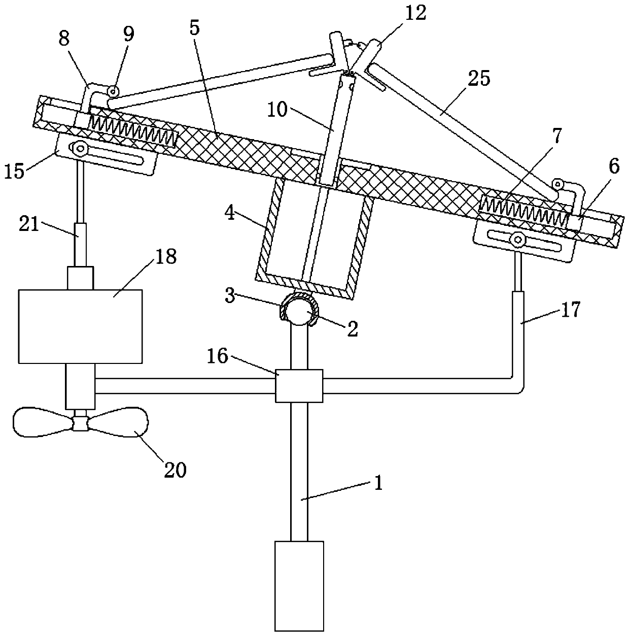
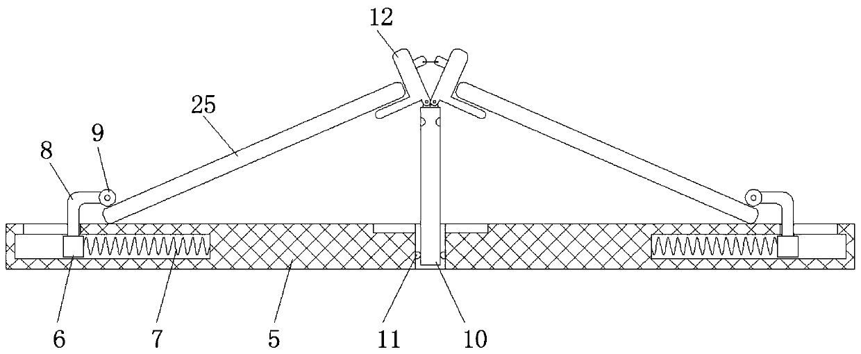
[0025] see Figure 1-5 , a solar panel support structure based on rotating centrifugal force, including a column 1, a ball 2, a limit sleeve 3, a support frame 4, a placement plate 5, a slider 6, a first spring 7, a bending rod 8, and a roller 9 , lifting rod 10, limit device 11, receiving plate 12, sliding rod 13, connecting rope 14, chute plate 15...


PUM


Abstract

The invention provides a solar panel support structure based on rotating centrifugal force, and relates to the technical field of solar photovoltaic. The invention discloses a solar panel support structure based on rotating centrifugal force. The solar panel support structure comprises a stand column, a ball is fixedly installed at the top end of the stand column, the top of the ball is wrapped with a limiting sleeve, a supporting frame is fixedly installed at the top end of the limiting sleeve, a containing plate is fixedly installed at the top end of the supporting frame, sliding blocks areslidably connected to the left side and the right side of the containing plate, and first springs are fixedly connected to the ends, close to the center of the containing plate, of the sliding blocks.According to the solar panel support structure based on the rotating centrifugal force, the working intensity of the solar panel during installation and replacement is reduced, the erection efficiency of the solar panel is improved, the orientation and the inclination angle of the solar panel can be adjusted, and the solar panel can tend to be in a horizontal state no matter whether the solar panel encounters wind power in any direction, so that the damage of the wind power to the solar panel is reduced.

Description

technical field [0001] The invention relates to the field of solar photovoltaic technology, in particular to a solar panel support structure based on rotational centrifugal force. Background technique [0002] Solar photovoltaic power generation is based on the principle of photovoltaic effect, using solar cells to directly convert sunlight energy into electrical energy. Whether it is used independently or connected to the grid for power generation, the photovoltaic power generation system is mainly composed of solar panels, controllers and inverters. , so if you want to use solar energy to generate electricity, you first need to install solar panels in a designated area. [0003] The brackets of traditional solar panels are made of steel pipes and various fasteners with bolts, and then the solar panels are fixed on the brackets. Therefore, whether it is installation or replacement of solar panels, it is necessary to Repeatedly loosen and tighten bolts with fasteners, the w...

Claims


Application Information

Patent Timeline
IPC IPC(8): H02S20/30F24S25/13F24S30/425
CPCF24S25/13F24S30/425H02S20/30Y02E10/47Y02E10/50
Inventor 曾贵
Owner 厦门科惟智能制造有限公司
Learn More