Multi-frequency antenna

A multi-frequency antenna and antenna element technology, applied in the direction of antenna, antenna coupling, antenna components, etc., can solve the problem of antenna layout area limitation, and achieve the effect of improving efficiency and saving antenna layout area.

Active Publication Date: 2022-07-05
ACER INC
View PDF10 Cites 0 Cited by
  • Summary
  • Abstract
  • Description
  • Claims
  • Application Information

AI Technical Summary

Problems solved by technology

However, under the appearance design of the narrow frame, the area available for the antenna element in the communication device is less and less
In addition, as more and more video-recording components (such as camera lenses and flash lights) are added to the top edge of the communication device, the layout area of ​​the antenna that can be used in the communication device is greatly limited.

Method used


Image

  • Multi-frequency antenna
  • Multi-frequency antenna
  • Multi-frequency antenna

Examples


Embodiment Construction

[0040] The term "coupled (or connected)" as used throughout this specification (including the claims) may refer to any direct or indirect means of connection. For example, if it is described in the text that a first device is coupled (or connected) to a second device, it should be interpreted that the first device can be directly connected to the second device, or the first device can be connected to the second device through other devices or indirectly connected to the second device by a connecting means. In addition, where possible, elements / components / steps using the same reference numerals in the drawings and embodiments represent the same or similar parts. Elements / components / steps that use the same reference numerals or use the same terminology in different embodiments may refer to relative descriptions of each other.

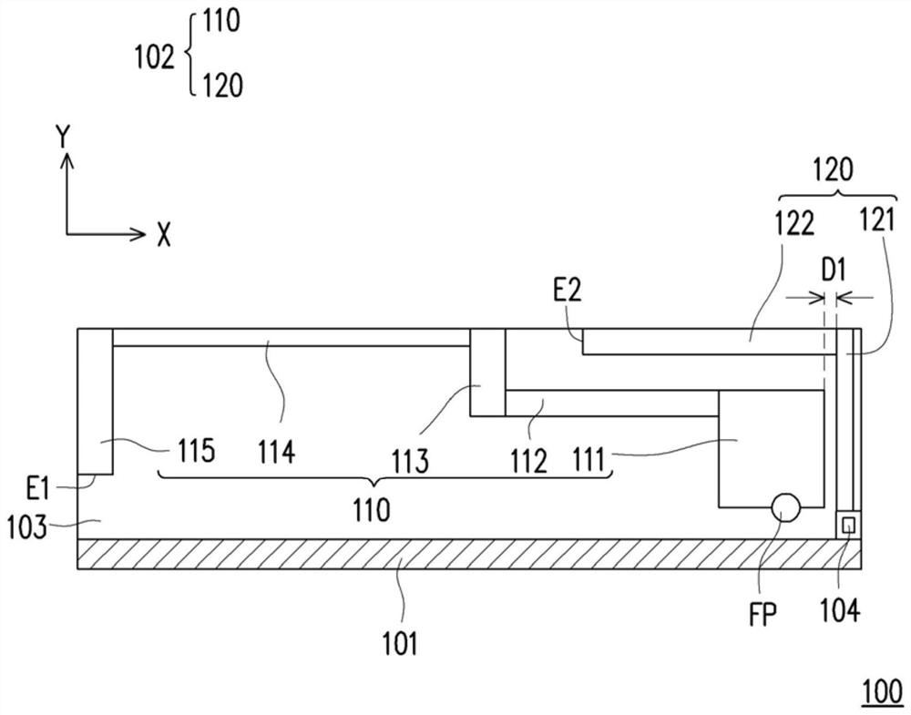
[0041] figure 1 It is a schematic top view of the multi-frequency antenna 100 according to an embodiment of the present invention. Please refer to fi...


PUM


Abstract

The invention provides a multi-frequency antenna, which includes a ground plane and an antenna element. The antenna element includes a first radiation portion and a second radiation portion. The first end of the first radiation part is coupled to the feeding point, and the second end of the first radiation part is the first open end. The first end of the second radiation portion is coupled to the ground plane, and the second end of the second radiation portion is a second open end. The second radiation portion is electrically disconnected from the first radiation portion, and there is a coupling distance between the second radiation portion and the first radiation portion. The antenna element operates in the first frequency band through the first radiating part, and operates in the second frequency band through the second radiating part, and the frequency of the first frequency band is lower than the frequency of the second frequency band.

Description

technical field [0001] The present invention relates to a multi-frequency antenna, in particular to a multi-frequency antenna operable in multiple frequency bands. Background technique [0002] In recent years, in order to meet consumers' demands for image quality and product appearance, the product design of communication devices has gradually developed towards a trend of narrow bezels. However, under the appearance design of the narrow frame, the area available for arranging the antenna element in the communication device becomes less and less. In addition, as more and more recording-related components (eg, camera lens, flash) are added to the top edge of the communication device, the available antenna layout area of ​​the communication device is greatly limited. [0003] Therefore, how to properly arrange the antenna elements in a limited layout area without affecting the communication quality is an important issue faced in the field of antenna design. SUMMARY OF THE I...

Claims


Application Information

Patent Timeline
Patent Type & Authority Patents(China)
IPC IPC(8): H01Q1/38H01Q1/48H01Q1/50H01Q1/52H01Q5/10H01Q5/20H01Q5/28H01Q5/307H01Q5/335H01Q5/50
CPCH01Q1/521H01Q1/38H01Q1/48H01Q1/50H01Q5/20H01Q5/307H01Q5/28H01Q5/10H01Q5/335H01Q5/50
Inventor 张琨盛
Owner ACER INC
Why Eureka
Try Eureka