Eureka AIR delivers breakthrough ideas for toughest innovation challenges, trusted by R&D personnel around the world.

Missile-borne SAR motion compensation method based on low-precision inertial navigation system

A motion compensation and missile-borne technology, applied in radio wave measurement systems, radio wave reflection/re-radiation, instruments, etc., can solve problems that do not take into account the complexity of the motion of the missile-borne platform

Active Publication Date: 2020-07-07
SHANGHAI RADIO EQUIP RES INST
View PDF19 Cites 9 Cited by
  • Summary
  • Abstract
  • Description
  • Claims
  • Application Information

AI Technical Summary

Problems solved by technology

[0003] Regarding the motion compensation of missile-borne SAR, most of the existing methods follow the uniform-velocity linear model of the airborne platform, without considering the complexity of the motion of the actual missile-borne platform; in terms of motion compensation algorithm, usually a single selection of motion sensor or echo data, each The disadvantages are as mentioned above

Method used


Image

  • Missile-borne SAR motion compensation method based on low-precision inertial navigation system
  • Missile-borne SAR motion compensation method based on low-precision inertial navigation system
  • Missile-borne SAR motion compensation method based on low-precision inertial navigation system

Examples


Embodiment Construction

[0032] In order to make the object, technical solution and advantages of the present invention clearer, the present invention will be described in further detail below in conjunction with specific embodiments and with reference to the accompanying drawings.

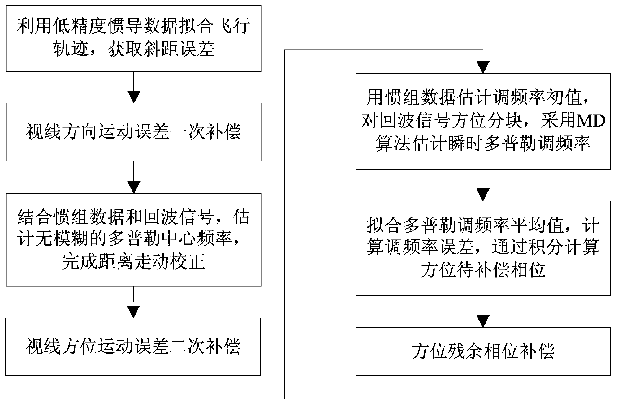
[0033] Such as figure 1 Show the flow chart of the method of the present invention, the present invention proposes a kind of ballistic SAR motion compensation method based on low precision INS, comprises the following steps:

[0034] Step S1, using the low-precision inertial navigation measurement data to obtain the actual flight trajectory, fitting the ideal flight trajectory, and obtaining the slope distance error;

[0035] Usually, the three-dimensional velocity of the carrier output by inertial navigation is located in the northeast sky navigation coordinate system. Without loss of generality, assuming that the projectile is flying at a velocity V(t), the average velocity during its synthetic aperture period can be...


PUM


Abstract

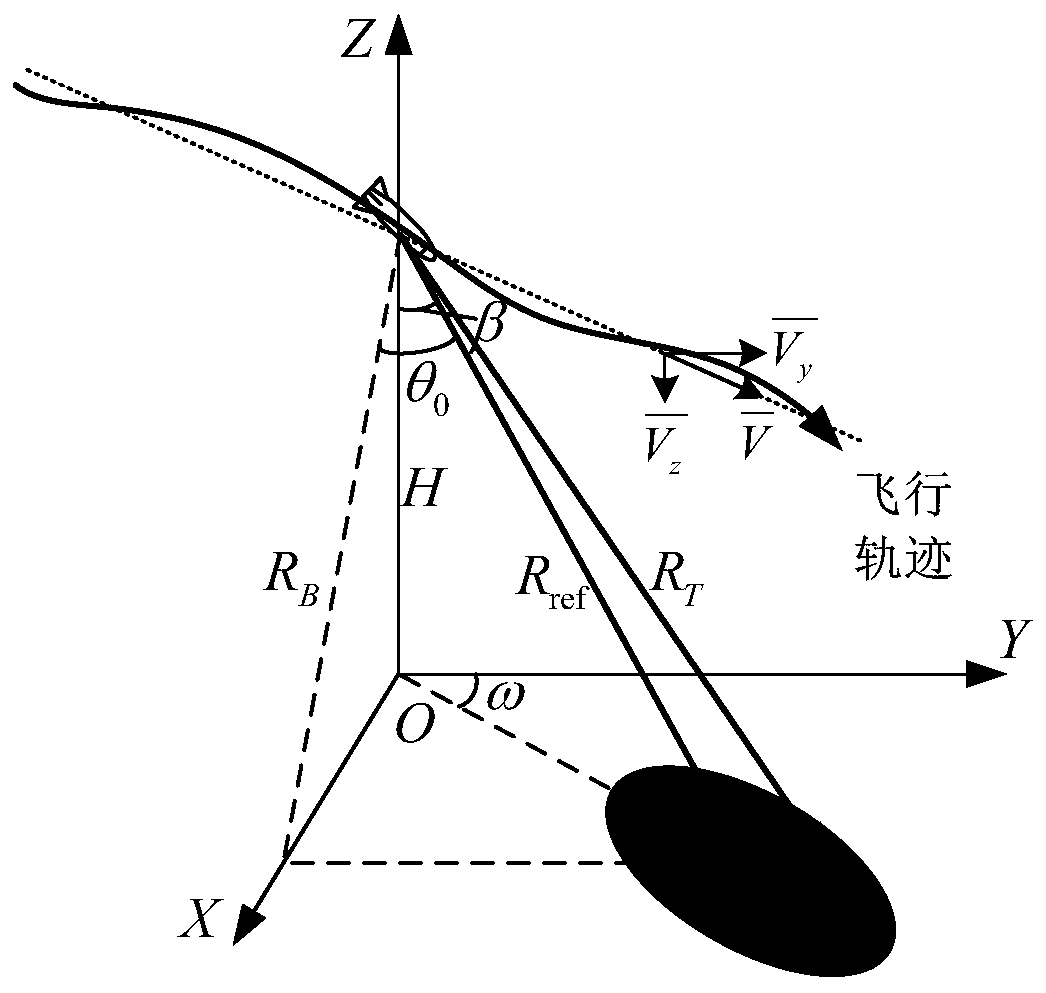
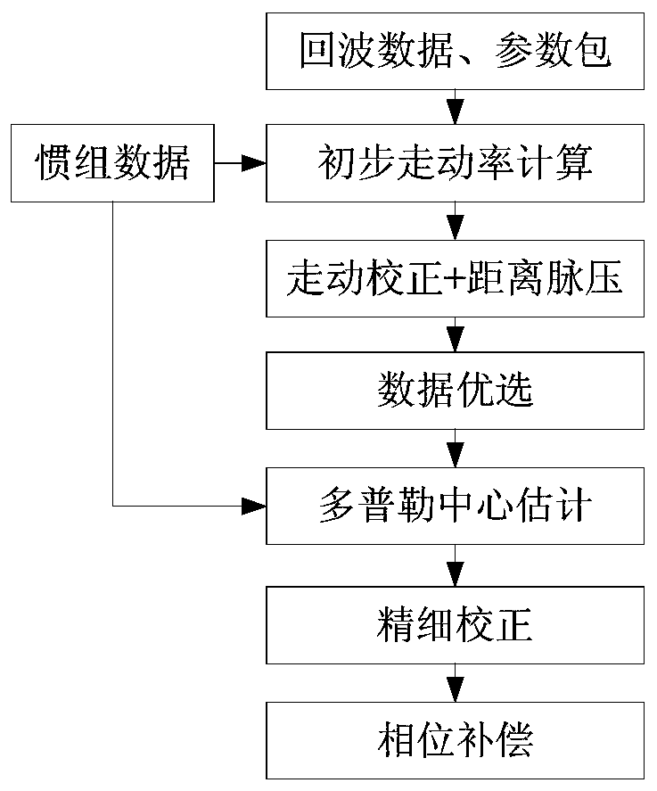
The invention relates to a missile-borne SAR motion compensation method, which comprises the steps of establishing a motion geometric model of missile-borne diving SAR imaging; integrating the actualmotion track of a carrier by using low-precision inertial measurement unit data according to a northeast sky speed measurement value, fitting an ideal track, calculating a position error, uniformly projecting the position error to the center of a wave beam, and completing consistent compensation of a sight-direction motion error by using a slant distance error of each reference point on a scene center line; combining the echo data and the inertial measurement unit data, giving a Doppler center initial value by the inertial measurement unit data, estimating a residual Doppler center by using acorrelation function method to obtain a real unambiguous Doppler center, and completing large-distance walk correction; after the distance is compressed, carrying out space-variant compensation of sight-direction motion errors caused by different slant distances on each distance unit; and combining the echo data and the inertial measurement unit data, giving a Doppler frequency modulation rate initial value according to the inertial measurement unit data, estimating the residual Doppler frequency modulation rate by an MD algorithm, calculating the azimuth residual phase and compensating to realize fine motion compensation of the missile-borne SAR.

Description

technical field [0001] The invention belongs to the technical field of radar signal processing, and in particular relates to a motion compensation method for missile-borne SAR based on a low-precision inertial navigation system. Background technique [0002] SAR imaging technology has become an important technology for precise guidance and strike, and it can work all-weather and all-day without being restricted by the use environment. The missile-borne platform is different from the airborne and space-borne platforms. Its application scenarios determine its high-speed, high-maneuverability, and non-linear trajectory characteristics. That is to say, the missile body has vertical heading speed and acceleration during flight, which will cause echo There are problems such as long-distance migration, geometric deformation, and large changes in Doppler parameters. SAR motion compensation methods are mainly divided into compensation methods based on motion sensors and compensation...

Claims


Application Information

Patent Timeline
IPC IPC(8): G01S7/41G01S13/90
CPCG01S7/415G01S13/9029G01S13/9019G01S13/9041
Inventor 夏慧婷张金强宫俊付朝伟
Owner SHANGHAI RADIO EQUIP RES INST
Why Eureka
Eureka Blog
Learn More