Metal crevice corrosion simulation device and metal crevice corrosion simulation experiment method
A technology for crevice corrosion and simulating devices, which is used in measurement devices, weather resistance/light resistance/corrosion resistance, instruments, etc., and can solve problems such as weak guidance in actual corrosion conditions.
- Summary
- Abstract
- Description
- Claims
- Application Information
AI Technical Summary
Problems solved by technology
Method used
Image


Examples
Embodiment 1
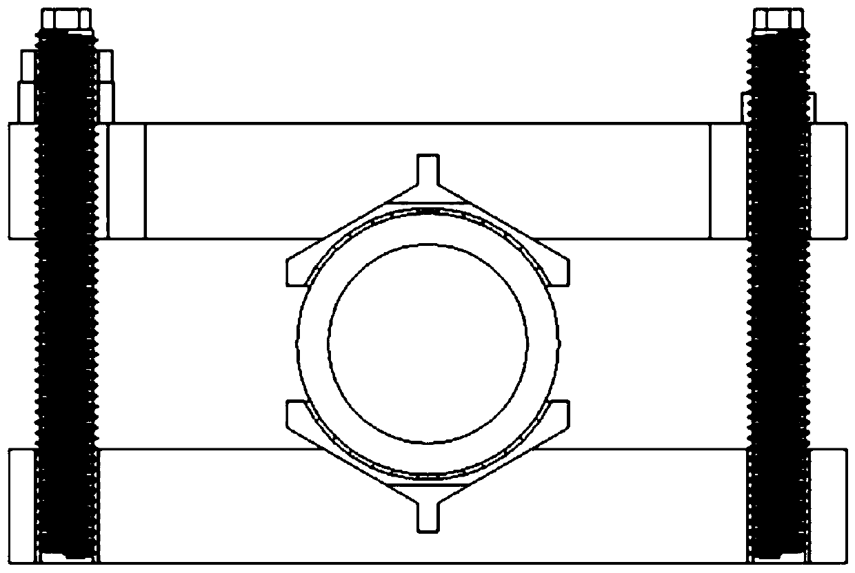
[0066] This embodiment provides a simulation device for metal crevice corrosion, referring to figure 1 and figure 2 As shown, it includes a bottom support plate 1 , a top cover plate 2 , a pressurized backing plate 3 , a support screw 4 and a prefabricated gap gasket 6 . An experimental pipe 7 is sandwiched between a pair of prefabricated gap gaskets 6 arranged up and down. The prefabricated gap gaskets 6 arranged up and down are fixed by the top cover plate 2 above and the bottom support plate 1 below. In this embodiment, the top cover plate 2 is in contact with the pressure pad 3 .
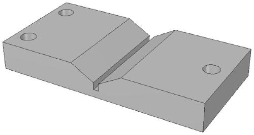
[0067] Refer to the shape of the top cover 2 Figure 4 As shown, the shape of the bottom support plate 1 refers to image 3 shown. In this embodiment, three installation holes are provided on the bottom support plate 1, refer to image 3 As shown, the two mounting holes on the left are used to install the support screw 4, and the support screw 4 supports the bottom support plate 1 and the...
Embodiment 2
[0093] This embodiment provides a simulation device for metal crevice corrosion in a symmetrical arrangement, referring to Figure 7 As shown, the only difference from Embodiment 1 is that in this embodiment, pressure pads 3 and support screws 4 are arranged symmetrically on both sides of the top cover plate 2, and the number of support screws 4 is four (two pairs). , each pair of adjacent supporting screw rods 4 is used to support the pressurized backing plate 3 and the bottom supporting plate 1 . The pressure pads 3 arranged on both sides of the top cover 2 apply downward pressure to compress the top cover 2 and the prefabricated gap gasket 6 to ensure that the experimental pipe 7 does not move sideways.
[0094] All the other structures are the same as in Example 1, and the method of use is also the same as in Example 1.
Embodiment 3
[0096] This embodiment provides a simulation device for asymmetrically arranged metal crevice corrosion, refer to Figure 8 As shown, it includes a bottom support plate 1 , a top cover plate 2 , a pressurized backing plate 3 , a support screw 4 , a first rotating shaft 8 , a second rotating shaft 9 , a T-shaped plate 10 and a prefabricated gap gasket 6 .
[0097] One end of the bottom supporting plate 1 is pierced with a first rotating shaft 8, the first rotating shaft 8 runs through the bottom supporting plate 1 transversely, and both ends of the first rotating shaft 8 are connected in series with rollers, and each roller is provided with a The support hole of the support screw 4 is installed, the top of the support screw 4 is fixedly connected with the pressure backing plate 3, the bottom end of the support screw 4 is fixedly connected with the support hole of the roller, and the support screw 4 can rotate around the first rotation axis 8, and the top One end of the cover pl...
PUM
 Abstract
Description
Claims
Application Information
 - R&D
- Intellectual Property
- Life Sciences
- Materials
- Tech Scout
- Unparalleled Data Quality
- Higher Quality Content
- 60% Fewer Hallucinations
Browse by: Latest US Patents, China's latest patents, Technical Efficacy Thesaurus, Application Domain, Technology Topic, Popular Technical Reports.
© 2025 PatSnap. All rights reserved.Legal|Privacy policy|Modern Slavery Act Transparency Statement|Sitemap|About US| Contact US: help@patsnap.com