Squeegee systems for printing presses
A printing press and scraper technology, applied in printing presses, general parts of printing machinery, printing, etc., can solve problems such as uneven ink, and achieve the effect of convenient replacement, convenient adjustment, and convenient disassembly.
- Summary
- Abstract
- Description
- Claims
- Application Information
AI Technical Summary
Problems solved by technology
Method used
Image

Examples
Embodiment approach 1
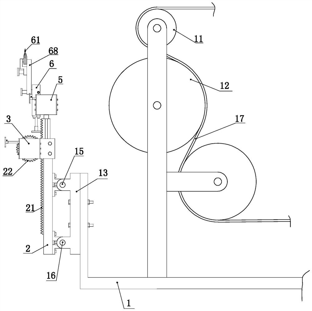
[0049] Such as figure 1 As shown, the doctor blade system of the printing machine includes a frame 1, a tension roller group and an anilox roller 12, and the tension roller group is composed of several tension rollers 11, and the tension roller group is used to tension the printing and dyeing products 17 on the On the mesh stick 12. A scraper mechanism is arranged on the frame 1, and the scraper mechanism is arranged on one side of the anilox roller.
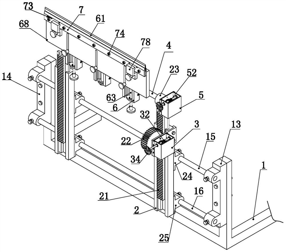
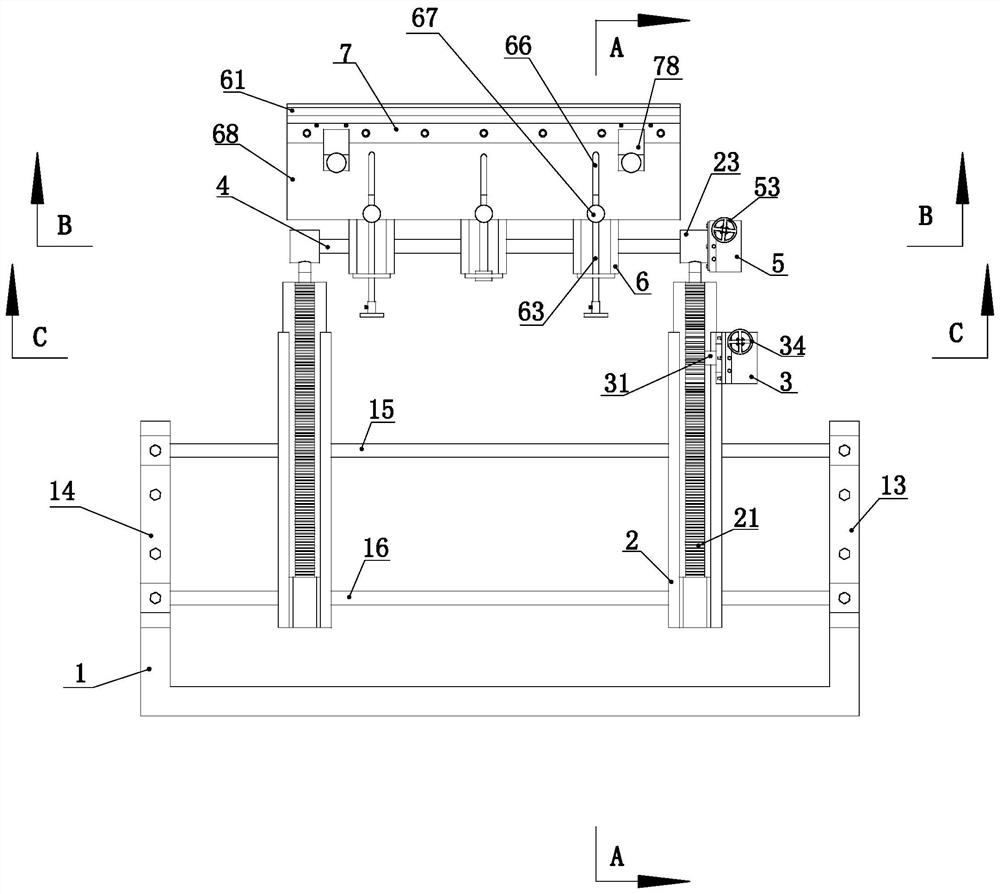
[0050] Such as Figure 1 to Figure 9 As shown, the scraper mechanism includes a rack seat 2, a rack 21, a gear 22, a first rotating shaft 31, a first control box 3, a first worm wheel 33, a first worm 32, a sleeve member 23, a knife holder shaft 4, a first Two manipulation boxes 5, the second worm gear 51, the second worm screw 52, the knife rest seat 6 and the blade 61.
[0051] Such as Figure 1 to Figure 9 As shown, the rack 21 is slidably connected to the rack seat 2 . The sliding direction of the rack 21 on the rack ...
Embodiment approach 2
[0063] The difference between Embodiment 2 and Embodiment 1 lies in the structure of the upper splint.
[0064] Definition, when used, the direction parallel to the anilox roller is the left and right direction; the terms "high" and "low" refer to the relative positional relationship in the working state.
[0065] Definition When in use, the end close to the anilox rod is the outer end, and the end away from the anilox rod is the inner end. When using this embodiment, it is preferred to adjust the blade to a state where the outer end is high and the inner end is low.
[0066] Such as Figure 10 to Figure 13 As shown, the outer end of the upper splint 7 is provided with a sump 75, and the left and right ends of the sump 75 are closed. A drain groove 76 is provided on the lower side of the upper splint 7 . The drain groove 76 is arranged in a manner that one end is higher and the other end is lower in the length direction. A plurality of diversion grooves 77 are arranged on t...
Embodiment approach 3
[0070] Such as Figure 14 As shown, the difference between this embodiment and the first embodiment is that the first crossbar 15 and the second crossbar 16 are slidably connected between the first support 13 and the second support 14 . The first cross bar 15 and the second cross bar 16 can reciprocally slide along the length direction. The frame 1 is provided with a driving mechanism for driving the first cross bar 15 and the second cross bar 16 to reciprocate. By connecting the motor 18 on the frame 1, connecting a swing arm 8 on the rotating shaft of the motor 18, rotating a roller 81 at the end of the swing arm 8, and connecting a roller 81 at the end of the second cross bar 16 Guide block 9, a chute 91 is set on the guide block 9, the chute 91 is arranged in the up and down direction, and the roller 81 is arranged in the chute to form a driving mechanism for driving the reciprocating motion of the first crossbar and the second crossbar . The reciprocating movement of t...
PUM
 Abstract
Description
Claims
Application Information
 - R&D
- Intellectual Property
- Life Sciences
- Materials
- Tech Scout
- Unparalleled Data Quality
- Higher Quality Content
- 60% Fewer Hallucinations
Browse by: Latest US Patents, China's latest patents, Technical Efficacy Thesaurus, Application Domain, Technology Topic, Popular Technical Reports.
© 2025 PatSnap. All rights reserved.Legal|Privacy policy|Modern Slavery Act Transparency Statement|Sitemap|About US| Contact US: help@patsnap.com