Electromagnetic induction plug
An electromagnetic induction and plug technology, applied in circuits, electrical switches, electrical components, etc., can solve problems such as accidents, damage to insulating shells, and electric shocks, and achieve the effect of ensuring stability.
- Summary
- Abstract
- Description
- Claims
- Application Information
AI Technical Summary
Problems solved by technology
Method used
Image
Examples
Embodiment 1
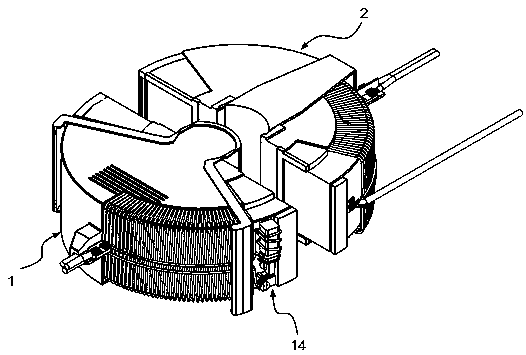
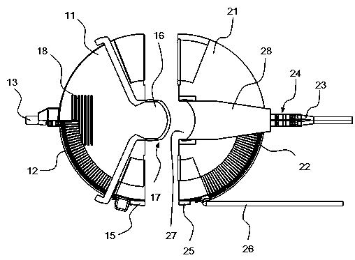
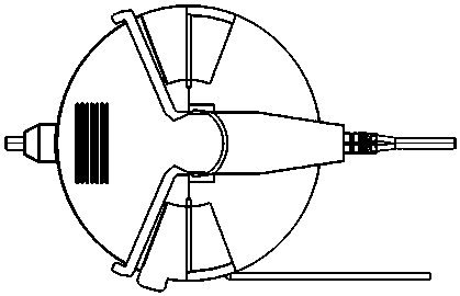
[0031] Embodiment 1, an electromagnetic induction socket, such as Figure 1 to Figure 3 As shown, it includes a plug 1 and a socket 2 that are plugged and matched. The plug 1 includes a shell A11, and a coil A12 is arranged inside the shell A11. Carry out electromagnetic induction, also be provided with overload protection mechanism 14 in the coil A12 circuit, overload protection mechanism 14 is used for disconnecting the coil A12 circuit when the electric current in the coil A12 is too large, as Figure 5 As shown, the overload protection mechanism 14 includes a coil C141. The coil C141 is connected in series with the coil A12 and wound on the magnetically permeable core C142. An armature 143 is provided below the magnetically permeable core C142. The armature 143 includes a first position of disconnection, a connection of When the armature 143 is in the second position, the drain joint 144 is connected. One end of the drain joint 144 is connected to the coil C141 circuit, an...
Embodiment 2
[0032] Embodiment 2 On the basis of Embodiment 1, the drain joint 144 is connected to the ground wire end and is arranged on the ground wire connecting plate A15, as figure 1 , figure 2 , Figure 4 As shown, the ground connection plate A15 is set on the shell A11, and oppositely, the shell B21 is provided with the ground line connection plate B25, and the ground line connection plate B25 is connected with the ground lead wire 26; when the plug 1 and the socket 2 are matched and connected , the ground connection plate A15 and the ground connection plate B25 are clamped.
Embodiment 3
[0033] Embodiment 3 refines the connection mode between plug 1 and socket 2 on the basis of embodiment 1, such as figure 1 As shown, the plug 1 and the socket 2 are matched with the groove 27 through the boss 16, and the boss 16 is arranged on the housing A11, and correspondingly, the housing B21 is provided with a groove 27, and the groove 27 is provided with a slide plate 28 , the other end of the slide plate 28 is connected to the front push plate 241; as Figure 7 As shown, the corresponding sleeve buckle 17 on the boss 16, the buckle 17 includes a bayonet 171, the bayonet 171 is sleeved on the boss 16, and there are hooks 172 extending outwards at both ends of the opening. Kneading controls the opening of the bayonet 171 for easy insertion and removal; wedge-shaped bosses 173 are provided on both sides of the bayonet 171, and correspondingly, wedge-shaped slots 174 matching the wedge-shaped blocks 173 are fixed on both sides of the end surface of the groove 27.
[0034] ...
PUM
 Abstract
Description
Claims
Application Information
 - R&D Engineer
- R&D Manager
- IP Professional
- Industry Leading Data Capabilities
- Powerful AI technology
- Patent DNA Extraction
Browse by: Latest US Patents, China's latest patents, Technical Efficacy Thesaurus, Application Domain, Technology Topic, Popular Technical Reports.
© 2024 PatSnap. All rights reserved.Legal|Privacy policy|Modern Slavery Act Transparency Statement|Sitemap|About US| Contact US: help@patsnap.com


