
Multifunctional compression-shear testing machine

A testing machine, multi-functional technology, applied in the field of comprehensive testing system, can solve problems such as complex structure of press shears

Pending Publication Date: 2020-07-03
NANJING UNIV OF TECH +1
View PDF0 Cites 3 Cited by
  • Summary
  • Abstract
  • Description
  • Claims
  • Application Information

AI Technical Summary

Problems solved by technology

[0003] The purpose of the present invention is to overcome the complex structure of the existing compression shearing machine and provide a multifunctional compression shear testing machine

Method used


Image

  • Multifunctional compression-shear testing machine
  • Multifunctional compression-shear testing machine
  • Multifunctional compression-shear testing machine

Examples


Embodiment Construction

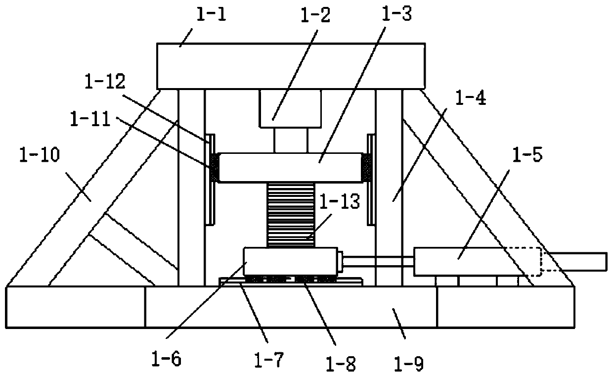
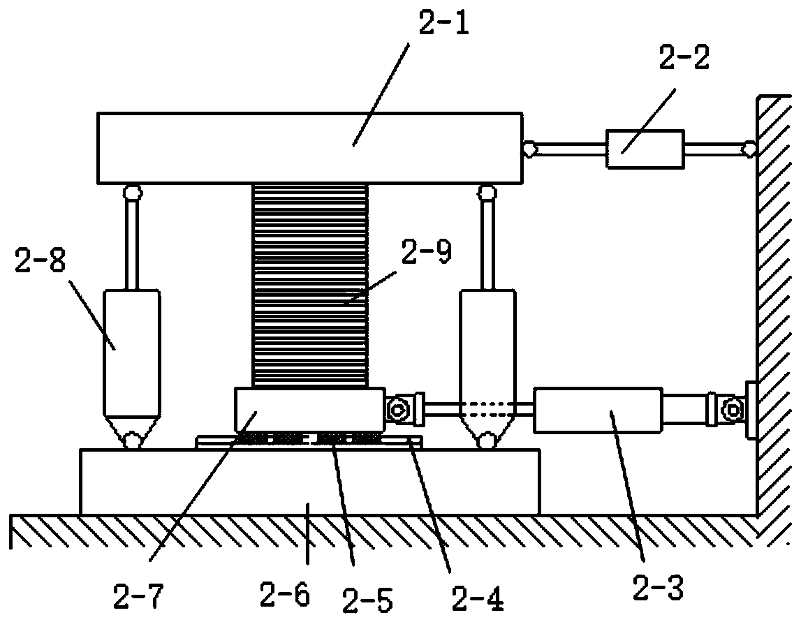
[0108] The present invention will be further described below in conjunction with the accompanying drawings and specific embodiments.

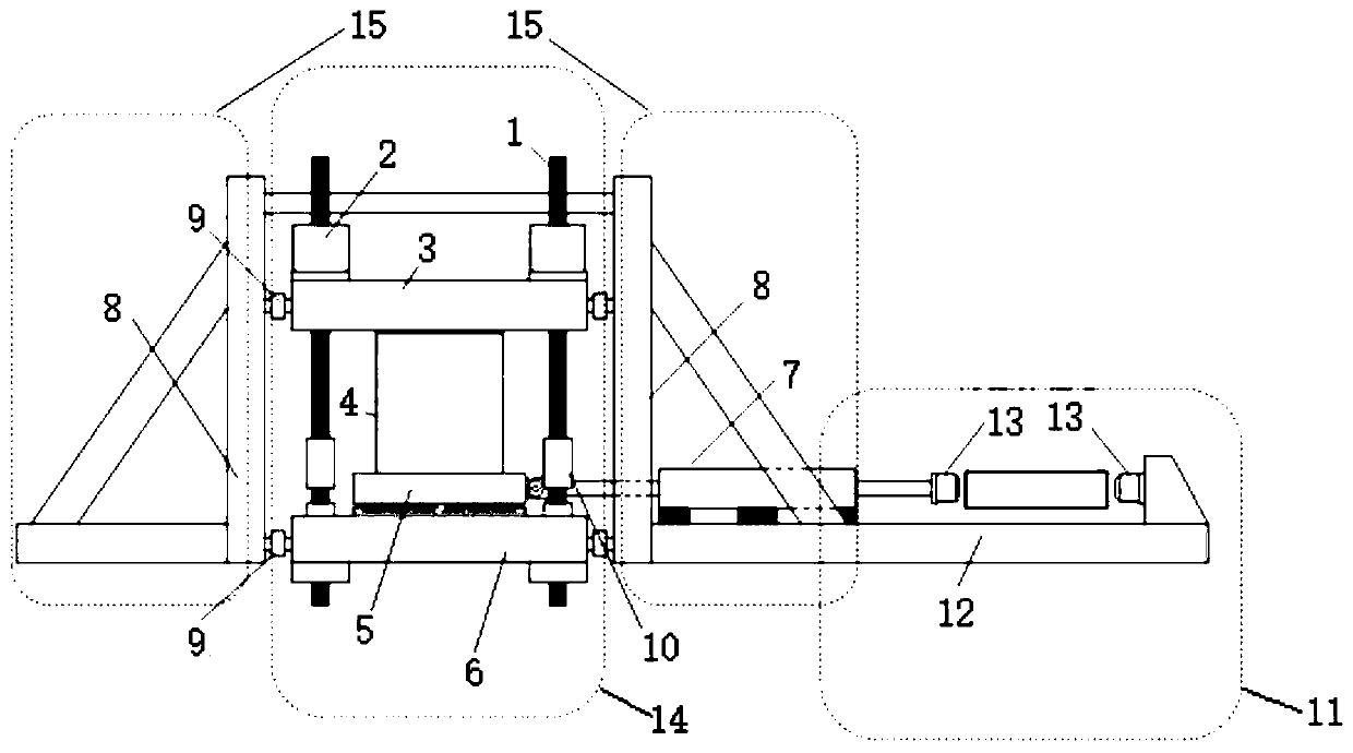
[0109] Such as image 3 As shown, a multifunctional compression-shear testing machine includes a vertical loading part 14, a lateral support part 15 and a function expansion device 11;

[0110] The vertical loading part 14 includes a column 1, a vertical loading actuator 2, an upper loading platform 3, a test piece 4, a lower loading platform 5, a loading base 6 and a horizontal actuator 7; the top of the column 1 or The bottom end is provided with a vertical loading actuator 2 that can apply a vertical force. An upper loading platform 3 is installed on the upper part of the column 1. Below the upper loading platform 3 is the loading space for the test piece 4. Below the test piece 4 is the lower loading space. Loading platform 5, the lower loading platform 5 is equipped with sliders at the bottom, and is installed on the loading base 6 throug...


PUM


Abstract

The invention discloses a multifunctional compression-shear testing machine. The multifunctional compression-shear testing machine comprises a vertical loading part, a lateral supporting part and a function extension device, wherein the vertical loading part comprises stand columns, a vertical loading actuator, an upper loading platform, a test piece, a lower loading platform, a loading base and ahorizontal actuator; the lateral supporting part comprises lateral triangular supports, the lateral triangular supports are arranged on the two sides or the single side, and the function extension device for achieving the function of a horizontal tension tester is additionally arranged on one side of the loading base. The multifunctional compression-shear testing machine not only can be used forconducting a compression-shear test, but also can be used as a horizontal tensile testing machine. Large-tonnage vertical loading is carried out through the four stand columns in the vertical direction, the triangular supports are arranged on the side surfaces, force sensors and a vertical loading frame are connected into a whole, and the testing machine can be used for friction-free loading of atest piece through a series of calculation.

Description

technical field [0001] The invention relates to the field of civil engineering, and is mainly aimed at a comprehensive test system for structural energy dissipation, shock absorption, shock isolation devices and various structural components. Background technique [0002] At present, conventional compression shearing machines are large in size and single in function, and cannot perform accurate compression shear tests. In order to meet the high-speed development and large-scale application of energy dissipation and vibration isolation, the experimental equipment must be suitable for various energy dissipation and vibration absorption products of different sizes, different tonnages, and different types. At the same time, it is also necessary to reduce the volume and weight of the shearing machine itself, so as to reduce the construction cost. Contents of the invention [0003] The purpose of the present invention is to overcome the complex structure of the existing compres...

Claims


Application Information

Patent Timeline
IPC IPC(8): G01N3/08G01N3/24G01N3/62
CPCG01N3/08G01N3/24G01N3/62G01N2203/0001G01N2203/0017G01N2203/0019G01N2203/0075G01N2203/0676G01N2203/0682
Inventor 万里苗苗汪博赵斌杨放缪汉良宋建军
Owner NANJING UNIV OF TECH
Learn More