
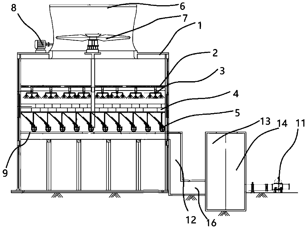
Combined single-side air inlet cooling tower

A cooling tower and combined technology, which is applied in the field of combined single-sided air inlet cooling towers, can solve the problems of increasing energy consumption, increasing the head of circulating water pumps, and the risk of negative pressure operation, so as to reduce noise and save land occupation area effect

Pending Publication Date: 2020-07-03
CHINA ENERGY ENG GRP GUANGDONG ELECTRIC POWER DESIGN INST CO LTD
View PDF6 Cites 6 Cited by
  • Summary
  • Abstract
  • Description
  • Claims
  • Application Information

AI Technical Summary

Problems solved by technology

In order to save floor space, the two columns of cooling towers are arranged back-to-back, but this changes the air intake mode of the cooling tower from double sides to single side. The method of increasing the height of the air inlet to increase the area of ​​​​the air inlet will cause the height of the entire cooling tower to increase, which will cause the height of the water distributor to increase, so that when the circulating water system is used to transport the cooling water to the water distributor, the circulation will be increased. The head of the water pump increases the energy consumption of operation
And the circulating water pump is usually arranged underground, there is a risk of negative pressure operation

Method used


Image

  • Combined single-side air inlet cooling tower
  • Combined single-side air inlet cooling tower
  • Combined single-side air inlet cooling tower

Examples


Embodiment Construction

[0025] The specific implementation manners of the present invention will be further described in detail below in conjunction with the accompanying drawings and embodiments. The following examples are used to illustrate the present invention, but are not intended to limit the scope of the invention.

[0026] In the description of the present invention, it should be understood that the orientation or positional relationship indicated by the terms "upper", "lower", "left", "right", "top", "bottom" etc. Orientation or positional relationship is only for the convenience of describing the present invention and simplifying the description, and does not indicate or imply that the referred device or element must have a specific orientation, be constructed and operated in a specific orientation, and thus should not be construed as a limitation of the present invention. It should be understood that the terms "first", "second", etc. are used in the present invention to describe various in...


PUM


Abstract

The invention provides a combined single-side air inlet cooling tower. The combined single-side air inlet cooling tower comprises a first tower body, a second tower body and a circulating water systemtower outer part, wherein the first tower body, the second tower body and the circulating water system tower outer part are abutted on the back; a first water remover, a first water distributor, a first packing layer and a first water collecting device are sequentially arranged in the first tower body from top to bottom, and a first water collecting tank is arranged at the lower part of the firstwater collecting device; a second water remover, a second water distributor, a second packing layer and a second water collecting device are sequentially arranged in the second tower body from top tobottom, and a second water collecting tank is arranged at the lower part of the second water collecting device; and the first water collecting tank and the second water collecting tank are simultaneously connected with a water collecting tank, the water collecting tank communicates with the circulating water system tower outer part, and the circulating water system tower outer part is respectively connected with the first water distributor and the second water distributor. The combined single-side air inlet cooling tower provided by the invention has the advantages of saving energy consumption and improving the economic and environmental friendliness of the cooling tower on the basis of ensuring the cooling efficiency and the ventilation effect of the cooling tower.

Description

technical field [0001] The invention relates to the technical field of industrial cooling and refrigeration technology, in particular to a combined single-sided air inlet cooling tower. Background technique [0002] In industrial production and refrigeration processes, in the wet cooling tower, the external low-temperature air is cooled by exchanging heat with the cooling water. After the heat exchange, the temperature of the cooling water is reduced, and the low-temperature cooling water is recycled for the circulating water system. The wet cooling tower in the prior art generally includes a water distributor, a packing layer, a rain zone, and a sump. The cooling tower at the lower part of the rain zone is provided with an air inlet, and low-temperature air enters through the air inlet, and the low-temperature air passes through the rain zone sequentially from bottom to top. , packing layer and water distributor, and exchange heat with the cooling water distributed by the w...

Claims


Application Information

Patent Timeline
IPC IPC(8): F28C1/00F28F25/00F28F25/02F28F25/04F28F25/10
CPCF28C1/00F28F25/00F28F25/02F28F25/04F28F25/10F28F2025/005
Inventor 龙国庆毛卫兵杨志邹健李波江长平何小华张青民
Owner CHINA ENERGY ENG GRP GUANGDONG ELECTRIC POWER DESIGN INST CO LTD
Learn More