Braking device for vehicle
A brake device and parking brake technology, applied in the direction of brake transmission, brakes, vehicle components, etc., can solve the problems of difficult cover parts, hard to visually confirm cover parts, floor equipment obstacles, etc., and achieve easy visual confirmation Effect
- Summary
- Abstract
- Description
- Claims
- Application Information
AI Technical Summary
Problems solved by technology
Method used
Image
Examples
no. 1 Embodiment approach
[0056] Braking device
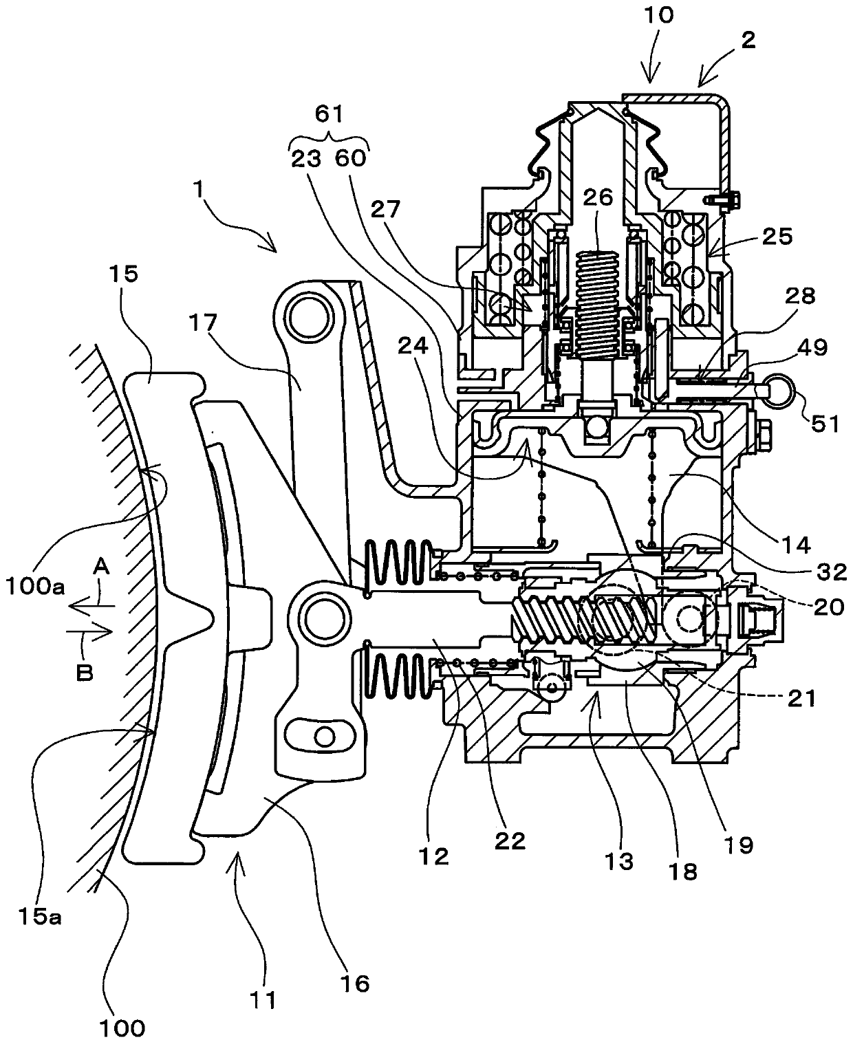
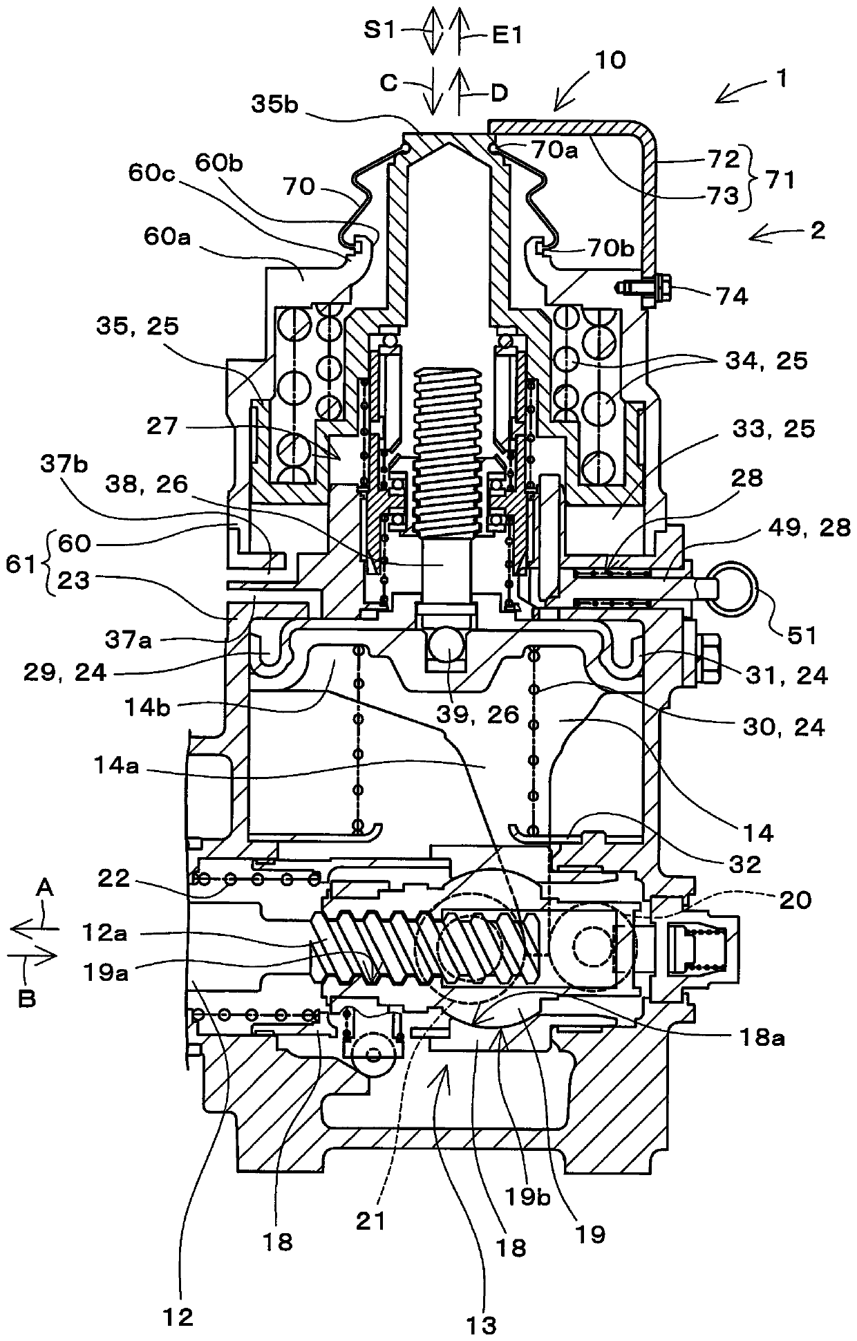
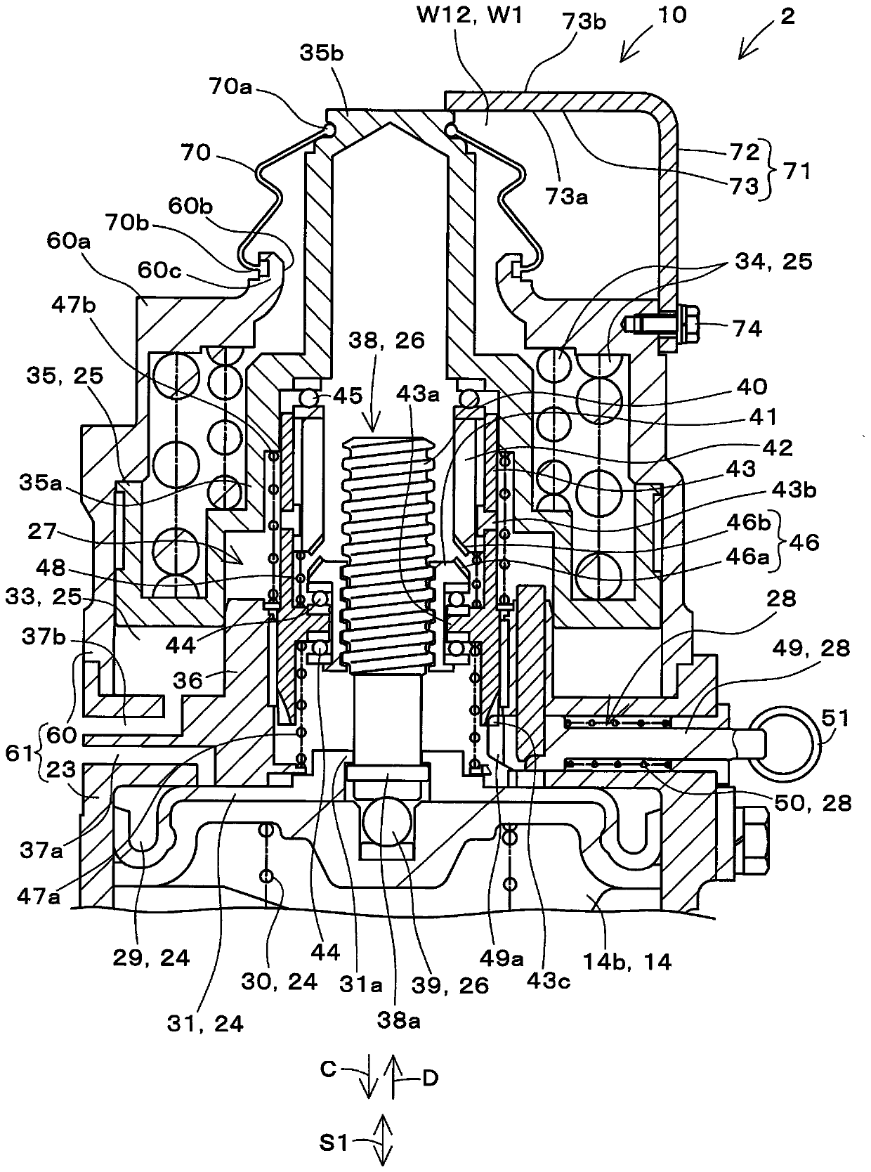
[0057] figure 1 It is a diagram including a partial cross section of the brake device 1 according to the first embodiment of the present invention. figure 2 will be figure 1 The illustrated part of the brake device 1 is an enlarged view showing a brake cylinder device 2 provided in the brake device 1 . figure 1 and figure 2 The illustrated brake device 1 is provided on a railway vehicle (not shown). in addition, figure 1 It is a figure which looked at the brake apparatus 1 from the axle direction of the wheel 100 of a railway vehicle in the state which installed the brake apparatus 1 in a railway vehicle.
[0058] The brake device 1 is configured as a tread brake device. The brake device 1 is configured to include a brake cylinder device 2 , a brake output unit 11 , a rod 12 , a rod support mechanism 13 , a rod drive unit 14 , and the like.
[0059] Furthermore, the brake device 1 is configured to drive the brake output unit 11 supported so a...
no. 2 Embodiment approach
[0170] Next, a second embodiment of the present invention will be described. In addition, in the following, differences from the first embodiment will be mainly described, and the same or similar reference numerals will be assigned to the same structures as those in the first embodiment, and descriptions will be omitted.
[0171] Figure 6 ~ Figure 8 It is a cross-sectional view showing main parts of a brake device 1A according to a second embodiment of the present invention. Image 6 shows the usual braking state, Figure 7 Shows the working state of the parking spring brake, Figure 8 It shows the state where the parking spring brake is temporarily released.
[0172] refer to Image 6 The display device 10A has a measurement member 71A, a first protrusion 75 , and a second protrusion 76 .
[0173] The measurement member 71A has a base 72 and a measurement main body 73A.
[0174] The distal end portion of the measurement main body 73A and the end surface of the one end ...
no. 3 Embodiment approach
[0191] Next, a third embodiment of the present invention will be described. Figure 9 ~ Figure 11 It is a side view showing main parts of a brake device 1B according to a third embodiment of the present invention, and a part is shown in cross section. Figure 9 shows the usual braking state, Figure 10 Shows the working state of the parking spring brake, Figure 11 It shows the state where the parking spring brake is temporarily released.
[0192] refer to Figure 9 , the display device 10B has a first protrusion 75B and a position sensor 77 .
[0193] The first protruding portion 75B is provided to indicate the relative position between the measuring member 71 and the second piston 35 . In addition, the first protruding portion 75B is provided to be in contact with the position sensor 77 .
[0194] The first protruding portion 75B protrudes from the end surface of the one end portion 35 b of the second piston 35 . The first protruding portion 75B is formed in, for examp...
PUM
 Abstract
Description
Claims
Application Information
 - R&D
- Intellectual Property
- Life Sciences
- Materials
- Tech Scout
- Unparalleled Data Quality
- Higher Quality Content
- 60% Fewer Hallucinations
Browse by: Latest US Patents, China's latest patents, Technical Efficacy Thesaurus, Application Domain, Technology Topic, Popular Technical Reports.
© 2025 PatSnap. All rights reserved.Legal|Privacy policy|Modern Slavery Act Transparency Statement|Sitemap|About US| Contact US: help@patsnap.com


