
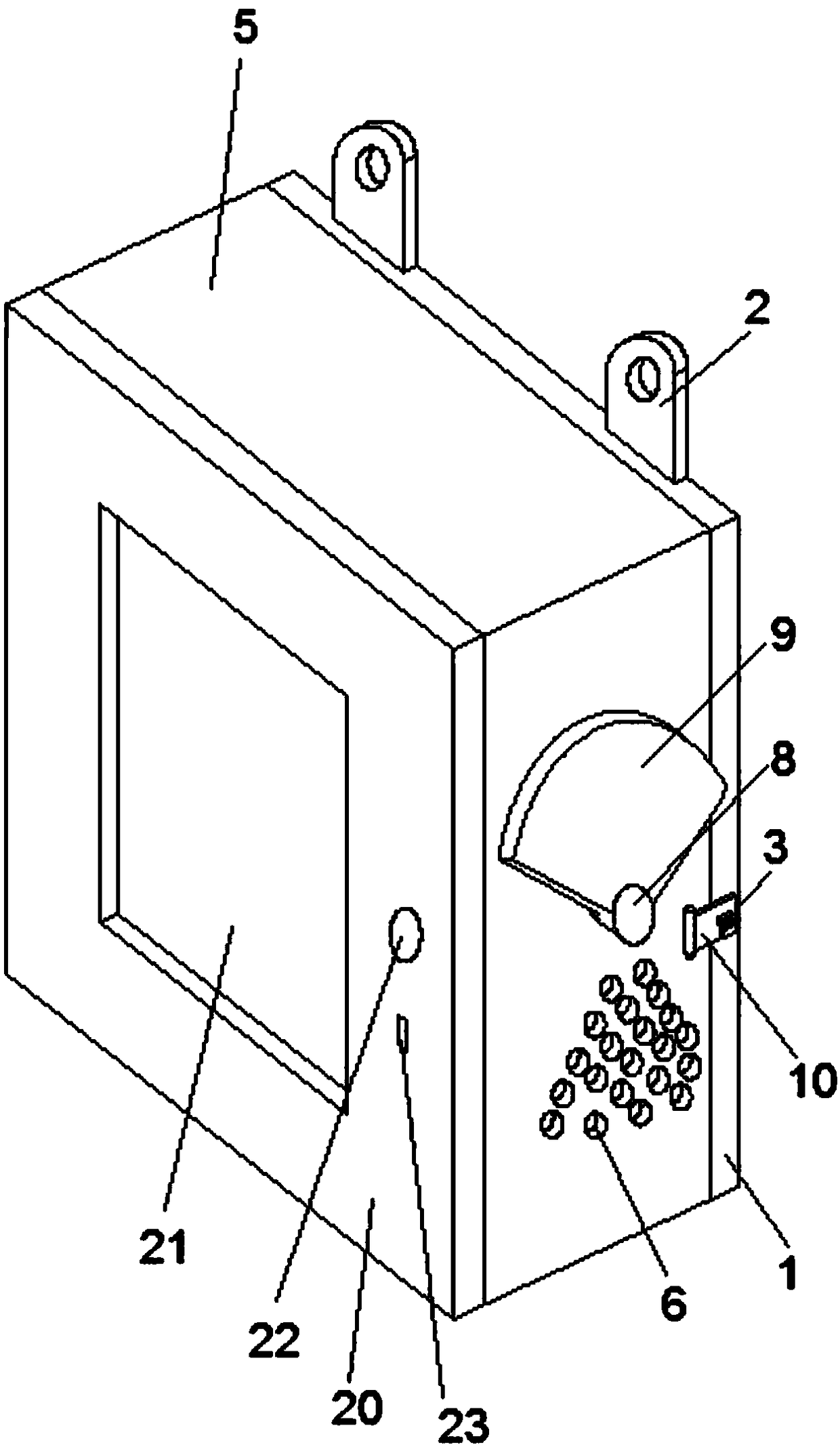
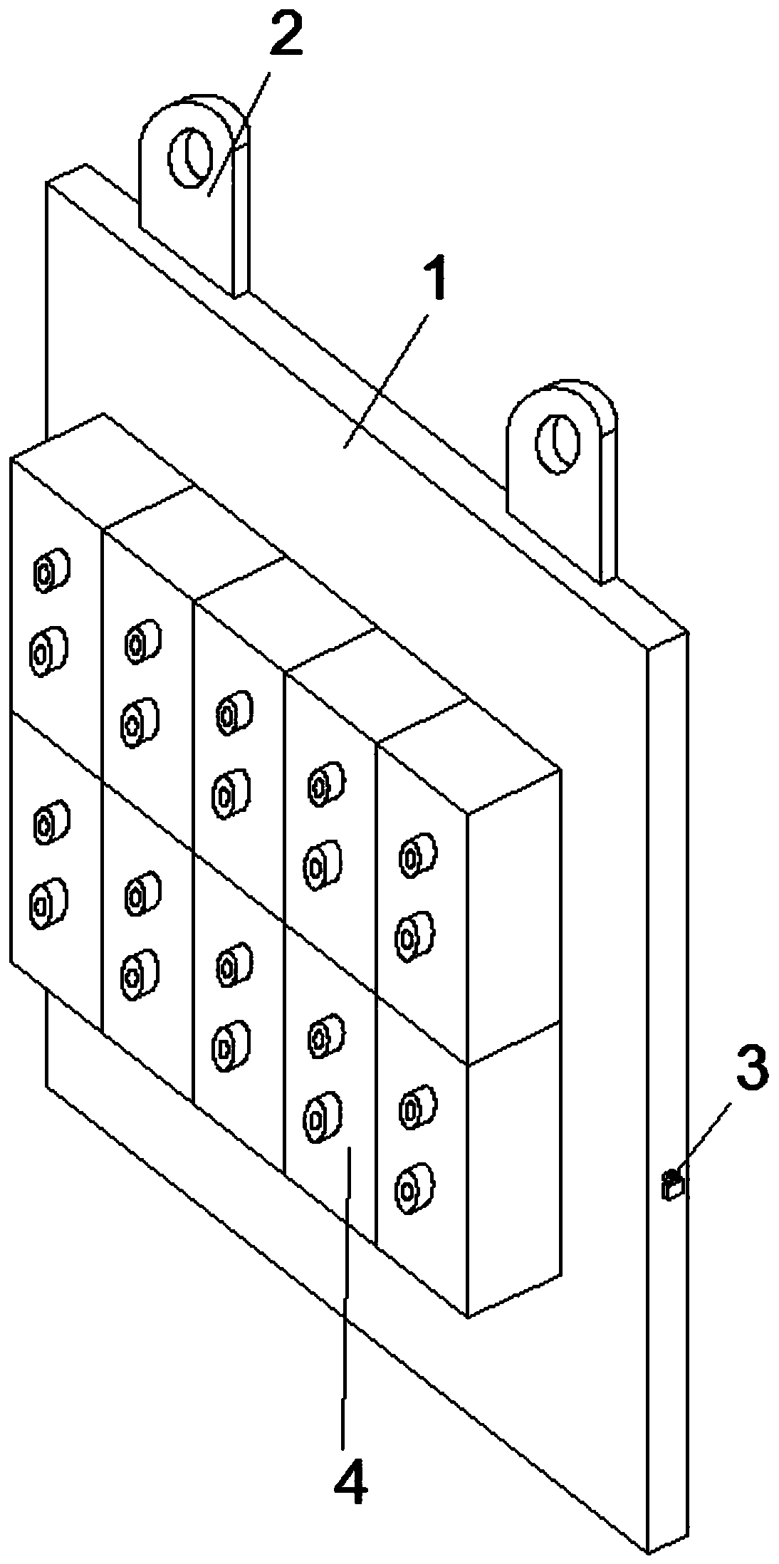
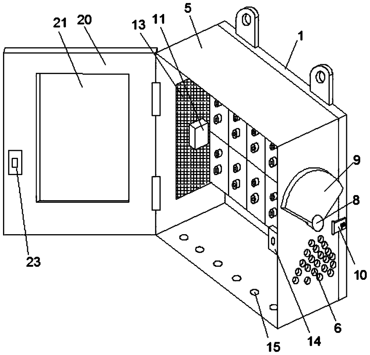
Multifunctional optical fiber distribution box for communication device

A technology for optical fiber distribution boxes and communication equipment, which is applied in the direction of light guides, optics, optical components, etc., and can solve the problems affecting the working stability of optical fiber distribution box components, single function of optical fiber distribution boxes, and limited versatility of distribution boxes, etc. Problems, to achieve the effect of convenient disassembly and installation, reduce speed and prolong service life

Active Publication Date: 2018-12-18
河北鹏博通信设备有限公司
View PDF4 Cites 0 Cited by
  • Summary
  • Abstract
  • Description
  • Claims
  • Application Information

AI Technical Summary

Problems solved by technology

When the optical fiber starts to work, the optical fiber adapter and optical fiber in the optical fiber distribution box will heat up during transmission. Since the optical fiber distribution box is generally closed, if the heat in the optical fiber distribution box cannot be evacuated, then the optical fiber distribution box The temperature inside the wiring box will rise, which will affect the working stability of the components in the optical fiber distribution box, leading to adverse consequences such as performance degradation. In addition, the existing optical fiber distribution box has a single function, which greatly limits It ensures the versatility of the wiring box installed in various occasions

Method used


Image

  • Multifunctional optical fiber distribution box for communication device
  • Multifunctional optical fiber distribution box for communication device
  • Multifunctional optical fiber distribution box for communication device

Examples


Embodiment Construction

[0026] In order to make the purpose, technical solutions and advantages of the embodiments of the present invention clearer, the technical solutions in the embodiments of the present invention will be clearly and completely described below in conjunction with the drawings in the embodiments of the present invention. Obviously, the described embodiments It is a part of embodiments of the present invention, but not all embodiments. Based on the embodiments of the present invention, all other embodiments obtained by persons of ordinary skill in the art without creative efforts fall within the protection scope of the present invention.

[0027] see Figure 1-6 : A multifunctional optical fiber distribution box for communication equipment, including a base plate 1, hanging ears 2 are symmetrically arranged on the left and right sides of the top of the base plate 1, an optical fiber adapter 4 is installed on the front side wall of the base plate 1, and a box is hinged at the front e...


PUM


Abstract

The invention relates to the technical field of outdoor communication devices, and specifically relates to a multifunctional optical fiber distribution box for a communication device. The multifunctional optical fiber distribution box comprises a bottom plate, wherein suspension loops are symmetrically arranged on the left and right sides of a top end of the bottom plate, an optical fiber adapteris installed on a front side wall of the bottom plate, a front end of the bottom plate is hinged with a box frame, a first vent hole and a second vent hole are respectively formed in the left and right side walls of the box frame, the first vent hole is located below the second vent hole, a rotating shaft is rotationally connected to the side wall of the box frame between the first vent hole and the second vent hole, a baffle is fixedly connected to the rotating shaft, the baffle is attached to the box frame, motor boxes are respectively arranged on inner side walls of the left and right sidesof the box frame, motors are installed in the motor boxes, and output shafts of the motors are fixedly connected with the rotating shaft. The multifunctional optical fiber distribution box provided by the invention has the advantages of simple structure, various functions and convenient installation and detachment, the structural design is convenient for the maintenance personnel to repair the device at a single point, meanwhile the multifunctional optical fiber distribution box has a heat dissipation degree adjustment function and has a visual observation window, thereby greatly facilitatingthe overall operation of the maintenance personnel, and accordingly, the multifunctional optical fiber distribution box is worthy of vigorous promotion.

Description

technical field [0001] The invention relates to the technical field of outdoor communication equipment, in particular to a multifunctional optical fiber distribution box for communication equipment. Background technique [0002] Optical fiber distribution box is a very commonly used component of outdoor communication equipment. It is directly placed in various outdoor natural environments. Operators can assemble various communication equipment in the distribution box. Therefore, optical fiber distribution boxes are widely used in outdoor communication equipment installations such as residential areas, commercial and residential buildings, and are one of the most widely used outdoor communication equipment installation components. [0003] With the popularization of fiber-to-the-home, in the optical communication access network, with more and more optical fiber access, it is necessary to use optical fiber distribution boxes to connect optical fibers to optical fibers. When t...

Claims


Application Information

Patent Timeline
Patent Type & Authority Applications(China)
IPC IPC(8): G02B6/44
CPCG02B6/4446
Inventor 李运茹
Owner 河北鹏博通信设备有限公司
Learn More