A pedal ladder device and vehicle

A pedaling and car ladder technology, applied in the field of pedaling ladder devices and vehicles, can solve the problems of increasing maintenance difficulty and cost, low frequency of use, and occupying the horizontal layout space of the whole vehicle, so as to improve the limited layout space, Reduce fatigue damage and improve the effect of layout space

Active Publication Date: 2021-08-17
FAW JIEFANG AUTOMOTIVE CO
View PDF6 Cites 0 Cited by
  • Summary
  • Abstract
  • Description
  • Claims
  • Application Information

AI Technical Summary

Problems solved by technology

[0003] 1. The traditional fixed pedal ladder device occupies a limited layout space outside the frame, and its use frequency is not high, so that the space utilization rate it occupies is not high;
[0004] 2. The traditional fixed pedal ladder device is generally arranged on the lateral outer side of the vehicle frame, and the usual use rate is low, but it occupies the lateral layout space of the vehicle, making it more difficult to arrange the lateral space of the vehicle with little margin;
[0005] 3. The traditional fixed pedaling ladder device is generally suspended on the outside of the frame with a cantilever beam structure. During the driving process, the pedaling ladder device is useless, but it will become the dynamic load of the frame and increase the load burden of the frame;
[0006] 4. If the traditional fixed pedaling ladder device is fixed on the outside of the post processor or the battery box, the pedaling ladder device forms a structure similar to a "guardrail", which reduces the maintenance accessibility of the systems and components inside it. Poor, when the user wants to repair the parts on the inner side of the pedal ladder, he needs to bypass the pedal ladder or remove it together, which increases the difficulty and cost of maintenance

Method used


Image

  • A pedal ladder device and vehicle
  • A pedal ladder device and vehicle
  • A pedal ladder device and vehicle

Examples


Embodiment Construction

[0043] In order to make the technical problems solved by the present invention, the technical solutions adopted and the technical effects achieved clearer, the technical solutions of the embodiments of the present invention will be further described in detail below in conjunction with the accompanying drawings. Obviously, the described embodiments are only the technical solutions of the present invention. Some, but not all, embodiments. Based on the embodiments of the present invention, all other embodiments obtained by those skilled in the art without creative efforts fall within the protection scope of the present invention.

[0044] In the description of the present invention, unless otherwise clearly specified and limited, the terms "connected", "connected" and "fixed" should be understood in a broad sense, for example, it can be a fixed connection, a detachable connection, or an integrated ; It can be a mechanical connection or an electrical connection; it can be a direct...


PUM


Abstract

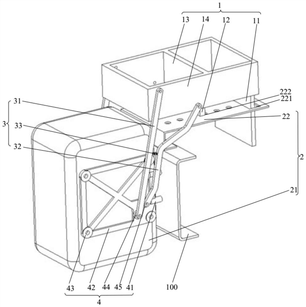
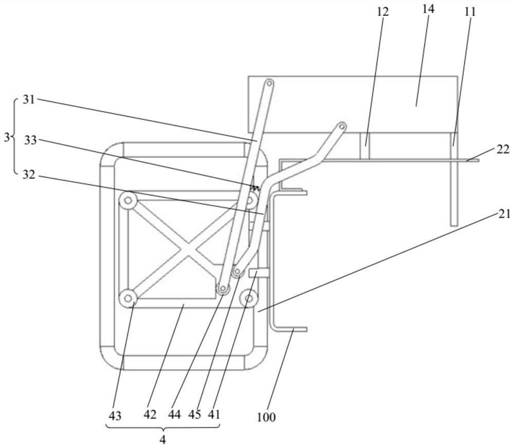
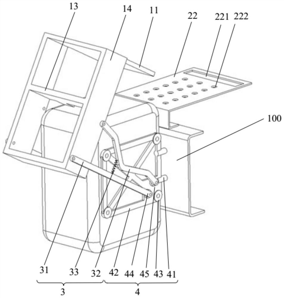
The invention belongs to the technical field of vehicles, and discloses a pedal ladder device and a vehicle. The pedal ladder device includes: a pedal ladder mechanism; a fixing mechanism, which is connected to the vehicle frame; a folding mechanism, which includes a first rotating rod, a second rotating rod and an elastic member, and the two ends of the elastic member are respectively connected to the first The rotating rod and the second rotating rod, the elastic member is always in a stretched state, one end of the first rotating rod is rotatably connected to the fixing mechanism, the other end is rotatably connected to the pedal ladder mechanism, and one end of the second rotating rod is rotatably connected to the fixing mechanism, The other end is rotatably connected to the pedaling ladder mechanism, and a quadrilateral structure is formed between the first rotating rod, the second rotating rod, the pedaling ladder mechanism and the fixing mechanism, and the pedaling ladder mechanism is configured to be turned over relative to the fixing mechanism so that the pedaling The ladder mechanism switches between a folded state and an unfolded state. The pedal ladder device has a damping deceleration effect during the folding process, and has good use comfort.

Description

technical field [0001] The invention relates to the technical field of vehicles, in particular to a pedal ladder device and a vehicle. Background technique [0002] At present, the existing pedal ladder devices for commercial vehicles are generally divided into fixed structure and folding structure. The pedal ladder device adopts a folding structure, which is prone to impact events caused by excessive force during the folding process. feeling poor. The pedaling ladder device adopts a fixed structure and is fixedly connected to the frame or other support structures, and the position cannot be moved, and has the following defects: [0003] 1. The traditional fixed pedal ladder device occupies a limited layout space outside the frame, and its use frequency is not high, so that the space utilization rate it occupies is not high; [0004] 2. The traditional fixed pedal ladder device is generally arranged on the lateral outer side of the vehicle frame, and the usual use rate is ...

Claims


Application Information

Patent Timeline
Patent Type & Authority Patents(China)
IPC IPC(8): B60R3/02
CPCB60R3/02
Inventor 王晓莲张学博丁淼
Owner FAW JIEFANG AUTOMOTIVE CO
Why Eureka
Try Eureka