
Clamping mechanism and clamping cutting platform

A clamping mechanism and clamping component technology, applied in the direction of clamps, workbenches, manufacturing tools, etc., can solve problems such as unstable clamping, and achieve the effect of solving unstable clamping and increasing the contact area.

Pending Publication Date: 2020-07-03
BEIJING SHENGFEIFAN ELECTRONIC SYST TECH DEV CO LTD
View PDF0 Cites 0 Cited by
  • Summary
  • Abstract
  • Description
  • Claims
  • Application Information

AI Technical Summary

Problems solved by technology

[0005] Embodiments of the present invention provide a clamping mechanism and a clamping platform to solve the problem of unstable clamping in the prior art

Method used


Image

  • Clamping mechanism and clamping cutting platform
  • Clamping mechanism and clamping cutting platform
  • Clamping mechanism and clamping cutting platform

Examples


Embodiment 1

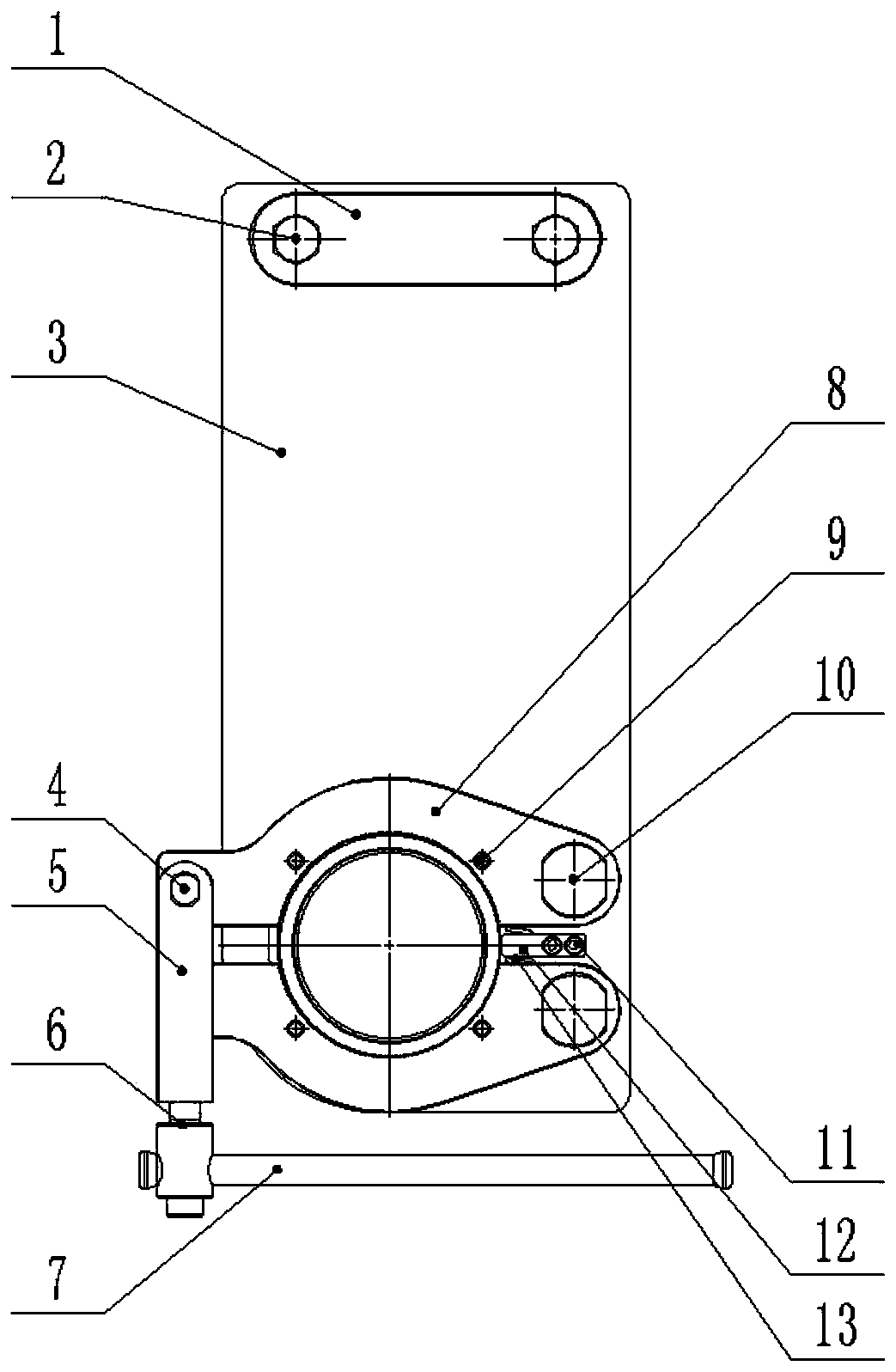
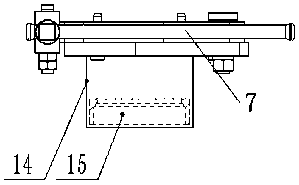
[0039] The first embodiment of the present invention provides a clamping mechanism, such as figure 1 As shown, the clamping mechanism includes a disassembly table 3, a locking assembly, a clamping assembly and a limit sleeve 14;

[0040] The clamping assembly is hinged on the disassembly table 3, and the limit sleeve 14 is fixed on the side opposite to the clamping assembly on the disassembly table 3, and penetrates through the clamping assembly;

[0041] The locking component is hinged to the clamping component;

[0042] Wherein, the locking assembly is tightened to open or lock the clamping assembly.

[0043] In this example, if figure 1 As shown, the clamping mechanism includes a table top pressure plate 1, a dismantling table top 3, a locking assembly, a clamping assembly and a limit sleeve 14. The table top pressure plate 1 is arranged on the disassembly table top 3, and both can be fixed by fixing bolts 2. The holding assembly is hinged on the disassembly table 3, and...

Embodiment 2

[0082] The second embodiment of the present invention provides a clamping and cutting platform, including the aforementioned clamping mechanism.

[0083] Specifically, this embodiment proposes a clamping and cutting platform for ammunition. The aforementioned clamping mechanism is provided on the clamping and cutting platform. Through the clamping and cutting platform, the ammunition can be further processed after the clamping mechanism completes the clamping of the ammunition. For example, for processes such as cutting, the stability and processing efficiency of the clamping platform can be further improved by providing the aforementioned clamping mechanism.


PUM


Abstract

The invention discloses a clamping mechanism and a clamping cutting platform. The clamping mechanism comprises a disassembling table top (3), a locking assembly, a clamping assembly and a limiting sleeve (14); the clamping assembly is hinged to the disassembling table top (3); the limiting sleeve (14) is fixed to the face, opposite to the clamping assembly, on the disassembling table top (3), andpenetrates through the clamping assembly; the locking assembly is hinged to the clamping assembly; and the locking assembly is loosened or tightened to unlock or lock the clamping assembly. Ammunitionis clamped through cooperation of the clamping assembly and the limiting sleeve (14), meanwhile, by arranging the limiting sleeve (14), the contact area with the ammunition can be enlarged, and thusthe problem of instable clamping in the prior art is solved.

Description

technical field [0001] The invention relates to the field of weapon accessories, in particular to a clamping mechanism and a clamping and cutting platform. Background technique [0002] With the advancement of science and technology and the rapid development of the weapon industry, the development of new ammunition is gradually accelerating, and the speed of ammunition replacement is also accelerating, which will produce a large number of waste ammunition. Its safety performance is reduced, and it is dangerous to continue to use it. At the same time, the storage of scrapped ammunition also brings great safety hazards to the ammunition warehouse, and it must be dismantled as soon as possible. [0003] Bazooka bombs, as one of the types of bombs that need to be scrapped and disassembled urgently, have many characteristics such as complex structure, tight installation, various types, and low stability. Tooling, tools. [0004] Since the bazooka projectiles are manufactured wi...

Claims


Application Information

Patent Timeline
Patent Type & Authority Applications(China)
IPC IPC(8): B25B5/16B25B5/04B25H1/08
CPCB25B5/163B25B5/166B25B5/04B25H1/08
Inventor 肖勇张志恒彭辉陈乐桑凯宁飞曹瑞刘俊岭赵晶
Owner BEIJING SHENGFEIFAN ELECTRONIC SYST TECH DEV CO LTD
Learn More