
Surgical instrument control method of a laparoscopic surgical robot

A surgical robot and surgical instrument technology, applied in the field of robotics, can solve problems affecting surgical efficiency, less degrees of freedom, and attenuation of transmission power, and achieve the effect of improving surgical efficiency and reducing difficulty

Active Publication Date: 2021-06-18
CHENGDU BORNS MEDICAL ROBOTICS INC
View PDF0 Cites 0 Cited by
  • Summary
  • Abstract
  • Description
  • Claims
  • Application Information

AI Technical Summary

Problems solved by technology

Especially for complex surgical operations, medical staff often need to operate surgical instruments for a long time
This is a challenge to the physical strength and energy of the doctor, which in turn affects the efficiency of the operation
[0003] The existing minimally invasive surgical instruments are often simple imitations of traditional open surgical instruments, with less freedom, poor flexibility, and often high friction inside the instrument, which leads to attenuation of transmission force and fatigue of the operator, especially It is the hand tremors caused by the operator's fatigue that will reduce the accuracy of the operation

Method used


Image

  • Surgical instrument control method of a laparoscopic surgical robot
  • Surgical instrument control method of a laparoscopic surgical robot
  • Surgical instrument control method of a laparoscopic surgical robot

Examples


Embodiment 1

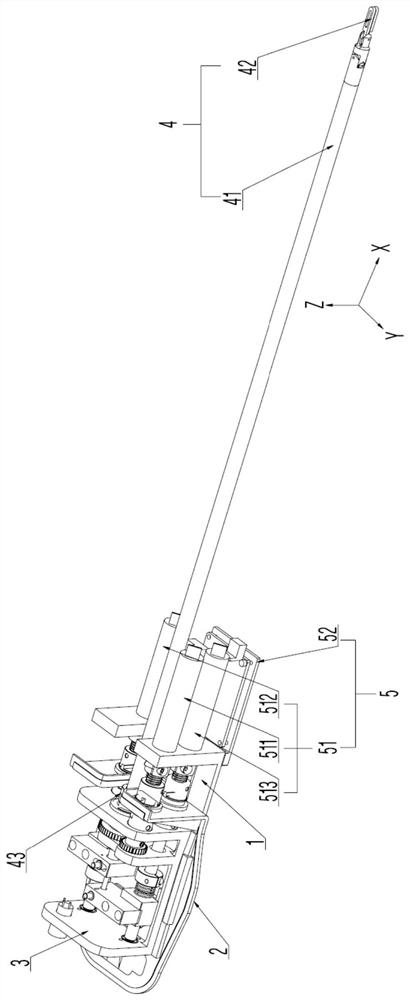
[0098] In a first embodiment of the invention, a surgical instrument 42 has a first degree of freedom (eg, an endoscope). Here, the first degree of freedom of the surgical instrument 42 means that the surgical instrument 42 can rotate around the axis of the instrument shaft 41 of the instrument connection mechanism 4 as the rotation axis (ie, along the X-axis direction). The first degree of freedom of the surgical instrument 42 can mimic the rotational motion of a human arm.

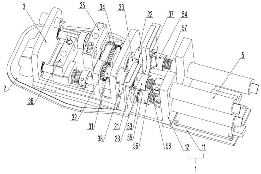
[0099] In this embodiment, the power source 51 of the driving mechanism 5 includes a first motor 511 , and the output shaft of the first motor 511 is disposed in the first hole 121 on the side wall of the fixing seat 12 of the driving seat 1 . In order to improve space utilization, the axial direction of the instrument shaft 41 , the axial direction of the first motor 511 and the length direction of the fixing seat 12 are the same.

[0100] Specifically, the power transmission mode of the first motor 51...

Embodiment 2

[0124] In the second embodiment of the present invention, the surgical instrument 42 has a second degree of freedom (such as a scalpel that cuts only at designated locations). Here, the second degree of freedom of the surgical instrument 42 means that the surgical instrument 42 can be deflected around the Z-axis. The second degree of freedom of the surgical instrument 42 can imitate the deflection action of the human wrist joint.

[0125] In this embodiment, the power source 51 includes a second motor 512 , and the output shaft of the second motor 512 is disposed in the second hole 122 on the side wall of the fixing base 12 . In order to improve space utilization, the axial direction of the instrument shaft 41 , the axial direction of the second motor 512 and the length direction of the fixing seat 12 are the same.

[0126] In this embodiment, the power output by the second motor 512 is transmitted to the instrument rod 41 through the first lead screw 354 and the first seat 3...

Embodiment 3

[0155] In the third embodiment of the present invention, the surgical instrument 42 has a third degree of freedom (for example, surgical scissors that only cut at specified positions). Here, the third degree of freedom of the surgical instrument 42 means that the surgical instrument 42 can be opened and closed. The third degree of freedom of the surgical instrument 42 can imitate the closing and opening movements of human fingers.

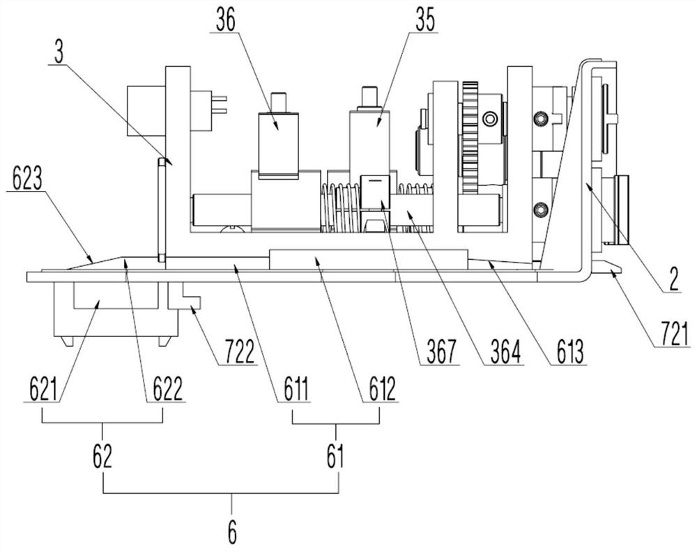
[0156] In this embodiment, the power source 51 includes a third motor 513 , and the output shaft of the third motor 513 is disposed in the third hole 123 on the side wall of the fixing base 12 . In order to improve space utilization, the axial direction of the instrument shaft 41 , the axial direction of the third motor 513 and the length direction of the fixing seat 12 are the same.

[0157] In this embodiment, the power output by the third motor 513 is transmitted to the instrument rod 41 through the second lead screw 364 and the second seat 36 ...


PUM


Abstract

The invention relates to a surgical instrument control method for a laparoscopic surgical robot, which includes adjusting the height and front and rear positions of the mechanical arm, collecting the rotation angle information, deflection angle information and opening angle information of the control handle by monitoring equipment, and collecting the collected The information is sent to the main control unit; the main control unit analyzes the received information separately to determine the operator's arm rotation angle, wrist deflection angle and finger opening angle, and thus output the corresponding rotation control command and deflection The control command and the opening and closing control command are given to the slave control unit; the first control module of the slave control unit controls the first motor to drive the surgical instrument to rotate according to the rotation control command, and the second control module of the slave control unit controls the first motor according to the deflection control command. The second motor drives the surgical instrument to deflect, and at the same time, the third control module of the slave control unit controls the third motor to drive the surgical instrument to open and close according to the opening and closing control command.

Description

technical field [0001] The invention relates to the technical field of robots, in particular to a method for controlling surgical instruments of a laparoscopic surgical robot. Background technique [0002] In minimally invasive surgery, medical personnel are often required to manually cut, strip, suture and other operations on tissues. Especially for complex surgical operations, medical staff often need to operate surgical instruments for a long time to perform operations. This is a challenge to the doctor's physical strength and energy, which in turn affects the efficiency of the operation. [0003] The existing minimally invasive surgical instruments are often simple imitations of traditional open surgical instruments, with less freedom, poor flexibility, and often high friction inside the instrument, which leads to attenuation of transmission force and fatigue of the operator, especially It is the hand tremors caused by the operator's fatigue that will reduce the accura...

Claims


Application Information

Patent Timeline
Patent Type & Authority Patents(China)
IPC IPC(8): A61B34/37A61B17/00
CPCA61B17/00234A61B2017/00199A61B2017/00398A61B2017/0046A61B2017/00477A61B34/37A61B34/70A61B2034/301A61B2034/302A61B2034/305
Inventor 李耀李建辉陈超罗栓黎昌波
Owner CHENGDU BORNS MEDICAL ROBOTICS INC
Learn More