Force boosting device and force boosting method of projectile shuttle yarn clip

A force device and projectile yarn technology, applied in textiles, papermaking, textile, looms, etc., can solve the problems of uneven force on the arm of the yarn clamp, short service life, easy breakage of the arm, etc., to achieve force Equal and uniform, long service life, avoiding the effect of easy breaking of the arm

Active Publication Date: 2020-06-30
扬州市郭氏精密机械制造有限公司
View PDF10 Cites 0 Cited by
  • Summary
  • Abstract
  • Description
  • Claims
  • Application Information

AI Technical Summary

Problems solved by technology

[0003] However, the projectile yarn clamp prepared in this way is prone to the following problems: when the yarn clamp is deformed by applying pressure, the force on the arm of the yarn clamp is uneven, and stress concentration is likely to occur, which finally causes the problem that the arm is easily broken. After clamping on the machine, it is easy to break at the two arms, the force decays faster, and the service life is short

Method used


Image

  • Force boosting device and force boosting method of projectile shuttle yarn clip
  • Force boosting device and force boosting method of projectile shuttle yarn clip
  • Force boosting device and force boosting method of projectile shuttle yarn clip

Examples


Embodiment Construction

[0028] Below in conjunction with specific embodiment, further illustrate the present invention, it should be understood that these embodiments are only used to illustrate the present invention and are not intended to limit the scope of the present invention, after reading the present invention, those skilled in the art will understand the various equivalent forms of the present invention All modifications fall within the scope defined by the appended claims of the present application.

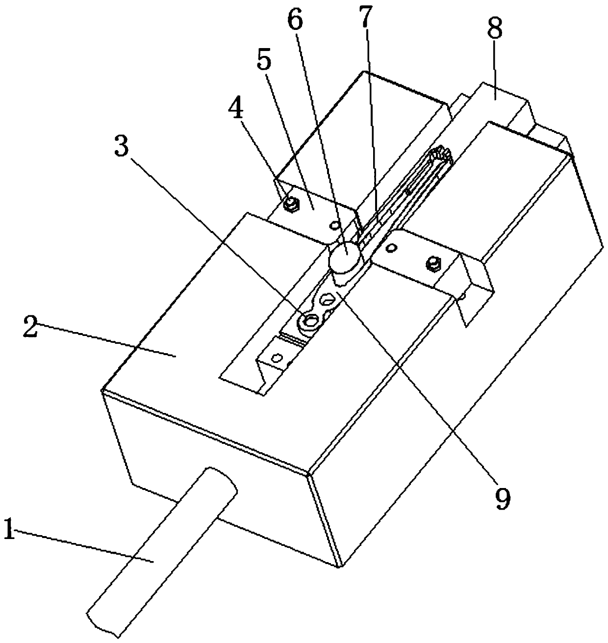
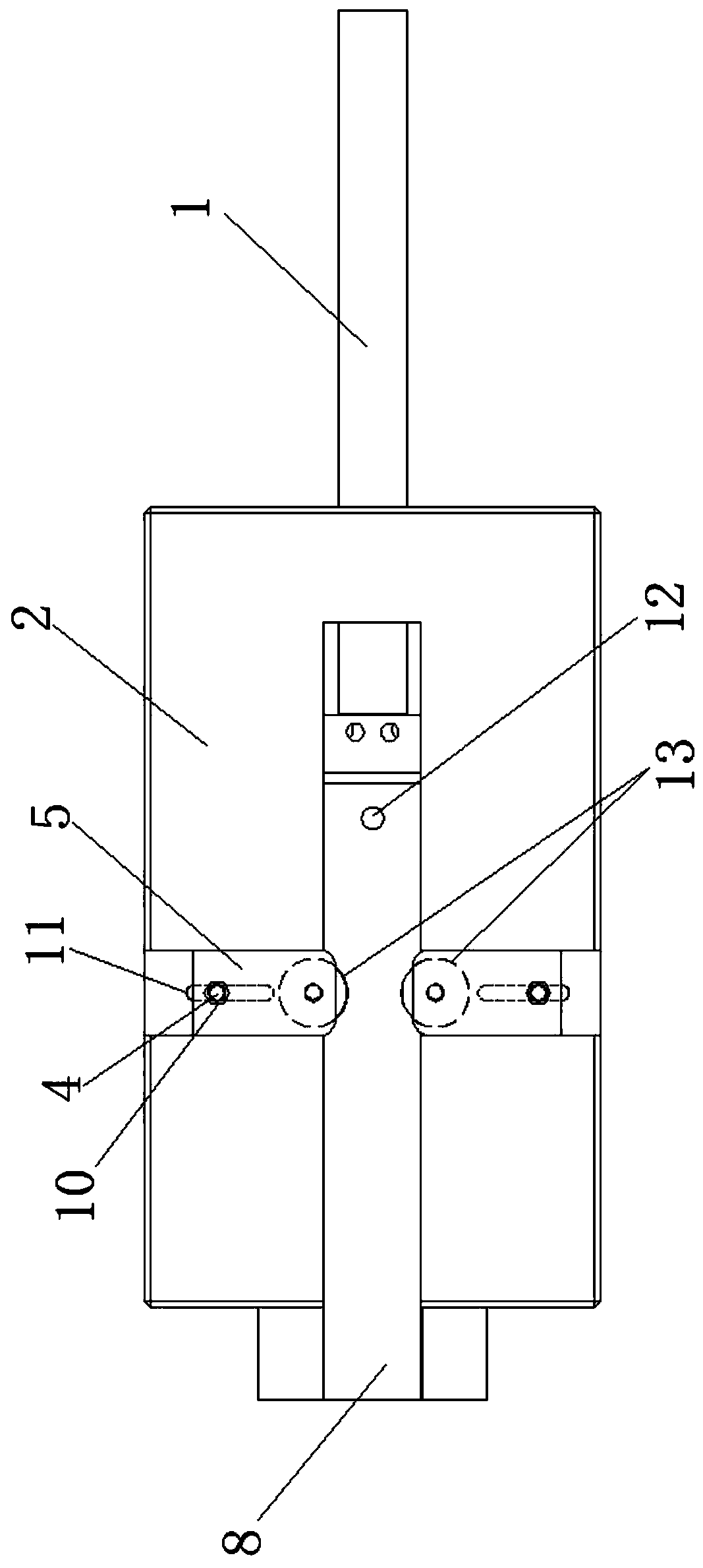
[0029] Such as Figure 1-7 As shown, a gripper grip force device includes a base 2 and a sliding groove 14 arranged on the base 2, a sliding seat 8 is slidably installed in the sliding groove 14, and the sliding seat 8 is provided to drive it along the length direction of the base 2. Sliding hydraulic cylinder, the piston rod 1 of the hydraulic cylinder is connected to the sliding seat 8; the upper end of the sliding seat 8 is placed with a yarn clip 9, the sliding seat 8 is provided with a pos...


PUM


Abstract

The invention discloses a force boosting device and force boosting method of a projectile shuttle yarn clip in the technical field of textile machinery. The force boosting device of the projectile shuttle yarn clip includes a base and a sliding groove arranged on the base; a sliding seat is slidingly installed in the sliding groove; the sliding seat is provided with a hydraulic cylinder that drives the sliding seat to slide along the length direction of the base; the piston rod of the hydraulic cylinder is connected to the sliding seat; a yarn clip is placed on the upper end of the sliding seat; the base is provided with two force boosting seats for performing force boosting on yarn clip; a force boosting space convenient for the placement of the yarn clip is arranged between the two forceboosting seats; the force boosting seats press against the arm of the yarn clip; the sliding seat is placed with a first force boosting core or a second force boosting core located between the two arms of the yarn clip; the second force boosting core is larger than the first force boosting core; the first force boosting core is used for supporting the location of one third from the shoulder of the yarn clip to the arm of the yarn clip; and the second force boosting core is used for supporting the middle from the shoulder of the yarn clip to the arm of the yarn clip. The advantage of the invention is that the force of the arm is balanced when the yarn clip is subjected to force boosting, so that the arm is not easy to break and has a long service life.

Description

technical field [0001] The invention relates to the technical field of textile machinery, in particular to a force applying device and a force applying method of gripper grippers. Background technique [0002] The projectile yarn clip is an important part of the projectile loom. The preparation method of the traditional projectile yarn clip is as follows: first make a round head, set a mounting hole in the head to connect with the bobbin case, and then make two arm parts , there is a wide distance of about 4mm between the ends of the two arms, and the ends of the two arms are respectively made with opposite clamping surfaces, that is, the jaws; then mechanical pressure is applied to the two arms of the yarn clamp, The two arms are deformed to have prestress, and the distance between the jaws becomes smaller. Finally, the deformed yarn clamp is installed in the bobbin case to work, and the weft yarn on one side of the loom is brought to the other side through the jaws. [00...

Claims


Application Information

Patent Timeline
Patent Type & Authority Applications(China)
IPC IPC(8): D03D47/24
CPCD03D47/24
Inventor 郭勐郭卫
Owner 扬州市郭氏精密机械制造有限公司
Why Eureka
Try Eureka