
Double-piston type pneumatic conveyer

A pneumatic conveying and double-piston technology, which is applied in the direction of conveyors, conveying bulk materials, transportation and packaging, etc., can solve the problems of smaller spraying distance, short conveying distance, and large conveying dust, so as to shorten the contact distance and reduce dust production , the effect of simplifying the structure

Active Publication Date: 2020-06-30
SHANDONG UNIV OF SCI & TECH
View PDF10 Cites 2 Cited by
  • Summary
  • Abstract
  • Description
  • Claims
  • Application Information

AI Technical Summary

Problems solved by technology

[0002] Pneumatic conveying equipment is often used in chemical industry, mining and coal mine underground to transport powder, fine particles and other materials inside the pipeline under the action of compressed air; in recent years, coal mine underground coal wall drilling pressure relief etc. Conveyors have been used, but most of the traditional pneumatic conveying equipment has problems such as fast wear, short conveying distance, and large conveying dust.
Among them, the sealing of the pneumatic conveyor is mainly realized by the pusher piston, but the seal is not tight after the pusher piston rubs against the material for a long time, so the spray distance becomes smaller, and there is still a large amount of dust when conveying materials that are prone to dust generation. In addition, it is necessary to further simplify the structure of the jet

Method used


Image

  • Double-piston type pneumatic conveyer
  • Double-piston type pneumatic conveyer
  • Double-piston type pneumatic conveyer

Examples


Embodiment Construction

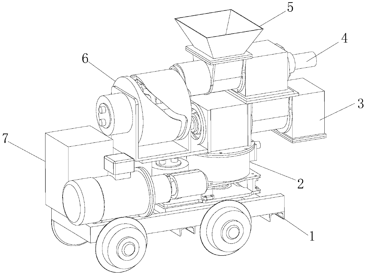
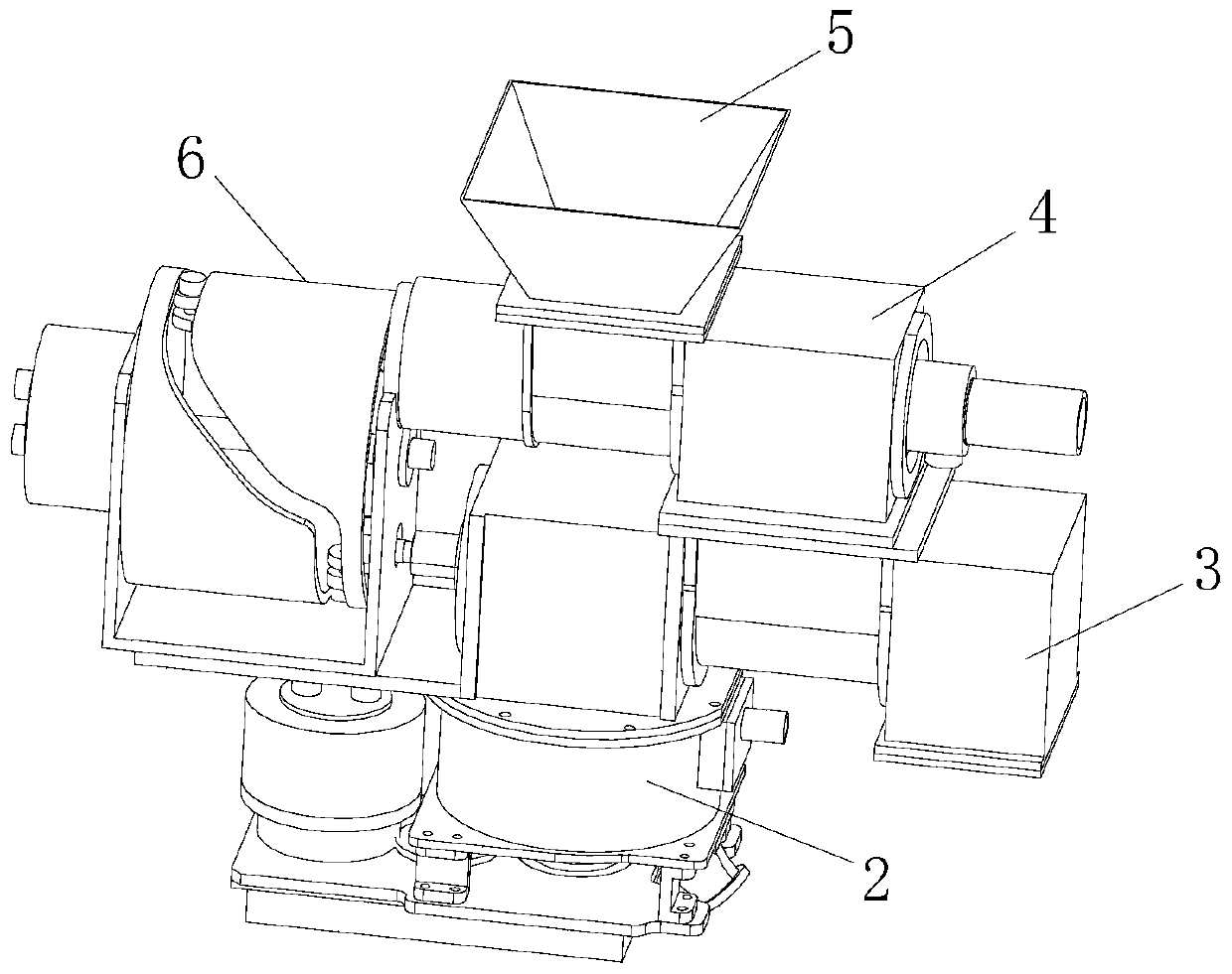
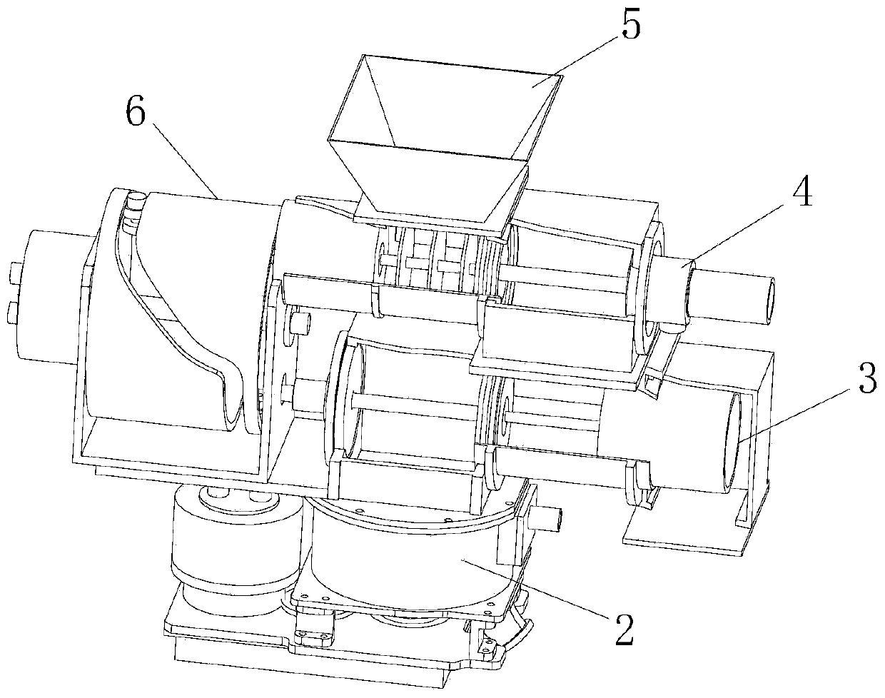
[0038] Such as Figure 1 to Figure 15 As shown, the specific implementation of a double-piston pneumatic conveyor provided by the present invention is as follows.

[0039] A double-piston pneumatic conveyor includes a frame 1, a rotor mechanism 2, an upper cylinder mechanism 4, a lower cylinder mechanism 3, a piston driving mechanism 6 and a hydraulic mechanism 7. The frame 1 is used to carry the structure of the pneumatic conveyor and assist the pneumatic conveyor in walking. The upper and lower cylinder mechanisms arranged in parallel are used to control the material supply to the rotor mechanism 2, especially the sealing design of the upper and lower cylinder mechanisms during the working process, to achieve It ensures good sealing and improves the service life of the equipment; the rotor mechanism 2 is used to evenly distribute materials and realize the continuous delivery of concrete, reducing pulses, and the hydraulic mechanism 7 provides power for each working part of t...


PUM


Abstract

The invention provides a double-piston type pneumatic conveyer, and relates to the technical field of pneumatic jetting devices. The double-piston type pneumatic conveyer comprises a rack, a rotor mechanism, an upper cylinder barrel mechanism, a lower cylinder barrel mechanism, a piston drive mechanism and a hydraulic mechanism. The hydraulic mechanism is arranged on the rear side of a bottom frame, the rotor mechanism is fixed to the front side of the bottom frame, the lower cylinder barrel mechanism is configured above the rotor mechanism, the upper cylinder barrel mechanism is configured above the lower cylinder barrel mechanism, and a hopper is mounted above an upper cylinder barrel of the upper cylinder barrel mechanism. The upper cylinder barrel mechanism and the lower cylinder barrel mechanism are arranged in the same direction, the piston drive mechanism simultaneously drives the two cylinder barrel mechanisms, and an upper sealing piston and a lower sealing piston are alternately located at a sealing position. Materials in all material bins are continuously jet through the rotor mechanism in the rotating process of a rotor. According to the pneumatic conveyer, the contradiction that pushing and sealing need to be achieved by the rotor and the pistons is solved, friction between the materials and the sealing pistons is reduced, the sealing effect is improved, the jetting distance is increased, dust generated in the conveying process is reduced, and the service life is prolonged.

Description

technical field [0001] The invention relates to the technical field of pneumatic injection devices, in particular to a double-piston pneumatic conveyor. Background technique [0002] Pneumatic conveying equipment is often used in chemical industry, mining and coal mine underground to transport powder, fine particles and other materials inside the pipeline under the action of compressed air; Conveyors have been used, but most of the traditional pneumatic conveying equipment has problems such as fast wear, short conveying distance, and large conveying dust. Among them, the sealing of the pneumatic conveyor is mainly realized by the pusher piston, but the seal is not tight after the pusher piston rubs against the material for a long time, so the spray distance becomes smaller, and there is still a large amount of dust when conveying materials that are prone to dust generation. In addition, it is necessary to further simplify the structure of the jet machine. Contents of the ...

Claims


Application Information

Patent Timeline
IPC IPC(8): B65G53/40
CPCB65G53/40
Inventor 马官国陈连军程卫民刘国明衣龙晓张存慧
Owner SHANDONG UNIV OF SCI & TECH
Learn More