Bi-component adhesive preparation device with magnetic stirring and overturning adhesive discharging functions

A magnetic stirring and agitator technology, which is applied to the surface coating liquid device, coating, etc., can solve the problems of wasting rubber material, affecting the use of glue, and high cost, and achieves extended service life, good mixing effect, and smooth glue path. broad effect

Active Publication Date: 2020-06-30
重庆津竹缘创新科技有限公司
View PDF26 Cites 2 Cited by
  • Summary
  • Abstract
  • Description
  • Claims
  • Application Information

AI Technical Summary

Problems solved by technology

However, due to the dense helical channel for cutting and mixing glue in the static mixing tube, the lumen is narrow, tortuous, and the surface area is large. For intermittent glue, especially quick-drying glue, it is very easy to cause the enrichment of cured products, which affects Glue flow rate and mixing effect will eventually cause blockage, and frequent replacement of static mixing tubes not only affects work efficiency, wastes rubber, and the cost of tube replacement is unbearable, but also affects environmental protection
The conventional dynamic agitator uses a motor to drive the paddle to mix the rubber in a finger-sized mixing dish. For the same reason, the paddle and the mixing dish will continue to adhere and deposit with the increase in use time and frequency, and some will start to solidify. The residual glue then causes clogging
In addition, the existence of the agitator in the mixing container affects the use of glue, and the conventional lifting agitator has a complicated structure and high cost
These problems have seriously affected the assembly line operation of the factory and affected the popularization and application of new environmentally friendly and quick-drying AB glue.

Method used


Image

  • Bi-component adhesive preparation device with magnetic stirring and overturning adhesive discharging functions
  • Bi-component adhesive preparation device with magnetic stirring and overturning adhesive discharging functions
  • Bi-component adhesive preparation device with magnetic stirring and overturning adhesive discharging functions

Examples


Embodiment 1

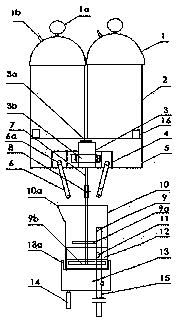
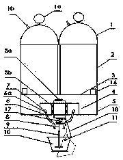
[0067] Such as figure 1 As shown, the storage barrels 2 containing components A and B respectively have an air pressure gauge 1a on the lid 1 and a pipe 1b connected to the air storage tank of the air compressor to maintain a constant pressure so that the glue flow and glue output are stable. The discharge pipes on the two storage tanks 2 are respectively connected to the inlet ends of the double-pipe feed valve 4, and the outlet ports 6a of the double-pipe feed valve 4 pass through the plate surface 5 supported by the support frame 16 and respectively connect with the two The conduit 6 is plugged in. A micro-motor 3 is arranged between the two conduits 6, and it is fixed on the plate surface 5 by the iron sheet 3a and the holding iron 3b. The rotating shaft 7 at the lower end of the motor 3 is connected with the stirring rod 9 through an adjustable coupling 8, The lower end of the stirring rod has a hinge 9a with a smaller rotation radius at a higher position, and a hinge 9b...

Embodiment 2

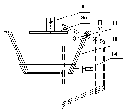
[0069] Such as figure 2 As shown, the two-component rubber material flowed quantitatively from the self-pressurized AB storage tank according to a certain ratio flows through the respective pipelines through the double-pipe feed valve fixed on a lower operating platform, and the double-pipe feed The outlet end of the valve is sleeved with a conduit, and the distance between the two outlets of the conduit is such that it can completely flow into the wide-mouth rubber nozzle. A motor is fixed directly above the wide-mouth rubber nozzle 10 by a support frame. There is a rotating shaft with a tapered lower end below it, and a hollow plastic stirring rod 9 is inserted on the rotating shaft with an interference at the upper end. The wide-mouth rubber nozzle 10 whose mouth diameter is larger than the height has a 25-45 degree inclination on the side wall can also use its taper to nest several same wide-mouth rubber nozzles in order to replace the innermost layer when necessary. A s...

Embodiment 3

[0071] The wide-mouth rubber nozzle 10 in the present invention can also be connected with the rotating shaft 11 or other overturning mechanisms through the extension structure, so that the wide-mouth rubber nozzle 10 can be installed and disassembled more easily; the shaft pin 11 can also be fixed directly or indirectly with the wide-mouth rubber nozzle Thereby rely on the rotation of control shaft 11 to realize overturning; slide block 13 can also be detachably fixedly connected with wide-mouth rubber nozzle 10, and the control part 14 of slide block 13 links to each other with overturning mechanism.


PUM


Abstract

The invention discloses a bi-component adhesive preparation device with magnetic stirring and overturning adhesive discharging functions, which is used for uniformly stirring and mixing as well as filling and dispensing a quick-drying adhesive according to a certain proportion with good fluidity. The bi-component adhesive preparation device with magnetic stirring and overturning adhesive discharging functions comprises material storage barrels for respectively holding components A and B, pipelines for enabling single-component adhesives to flow into a mixer, and the mixer, and is characterizedin that a double-control valve is arranged between the pipelines for two single-component adhesives to flow into the mixer; a wide-mouth adhesive nozzle serving as the mixer and a stirrer are arranged below the double-control valve; a mechanism for positioning and overturning the wide-mouth adhesive nozzle to pour out the adhesive at a determined position and can restore to the original positionis arranged; the stirrer consists of a stirring bar arranged in the wide-mouth adhesive nozzle and a controllable magnetic rotator arranged in a rotating body close to the bottom of the wide-mouth adhesive nozzle; and a mechanism for coordinated action is arranged between / among a valve body, a wide-mouth adhesive nozzle combination and / or the stirrer. Because an adhesive path in the mixer is wide,the inner wall is smooth and an adhesive discharging opening is formed in the upper part, the blockage of the adhesive path can be effectively avoided; the service life of the mixer can be greatly prolonged; moreover, the structure is simple; and the use is convenient.

Description

technical field [0001] The invention relates to a device for evenly stirring and mixing a two-component adhesive according to a certain ratio, and is especially suitable for filling or dispensing fast-drying adhesives with good fluidity. The present invention is a divisional application of Chinese patent application CN2018116498903. Background technique [0002] Existing two-component sizing equipment includes pneumatic or electric spraying machines, glue pouring machines, glue pouring machines, glue dispensers, glue guns, etc. Generally, gear pumps, air pumps or electronic balances are used to adjust the volume ratio or mass ratio. The glue of the components is mixed through a static mixing tube or a dynamic agitator and flows out from the glue outlet. It is suitable for two-component adhesives with slower reaction and better fluidity. However, due to the dense helical channel for cutting and mixing glue in the static mixing tube, the lumen is narrow, tortuous, and the sur...

Claims


Application Information

Patent Timeline
Patent Type & Authority Applications(China)
IPC IPC(8): B05C11/10
CPCB05C11/1036B05C11/10
Inventor 卢清友卢思竹袁小亚冉黎明李巧红邱顺
Owner 重庆津竹缘创新科技有限公司
Why Eureka
Try Eureka