IGBT protection circuit, method and device and three-phase inverter circuit
A protection circuit and device technology, applied in the field of IGBT protection circuit and three-phase inverter circuit, can solve the problems of limiting the working range of the inverter and the inability to fully utilize the output capacity of the IGBT.
- Summary
- Abstract
- Description
- Claims
- Application Information
AI Technical Summary
Problems solved by technology
Method used
Image
Examples
Embodiment 1
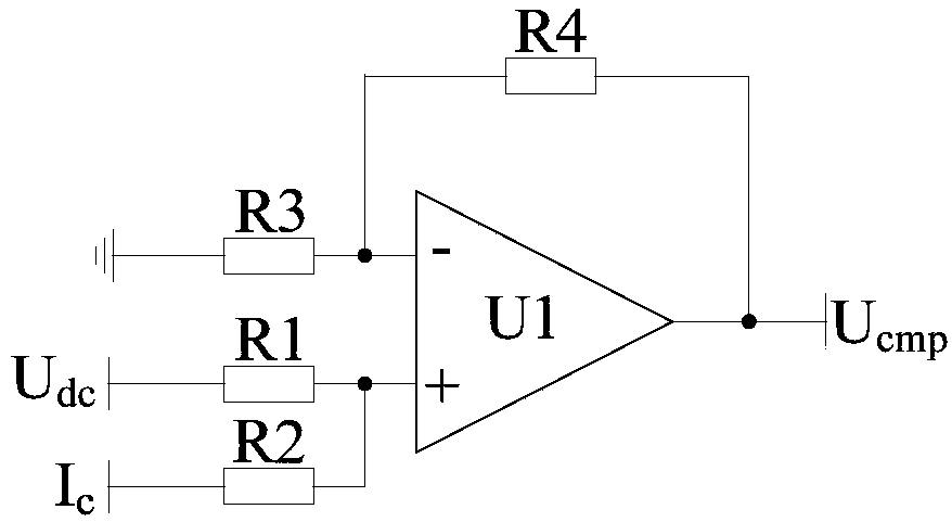
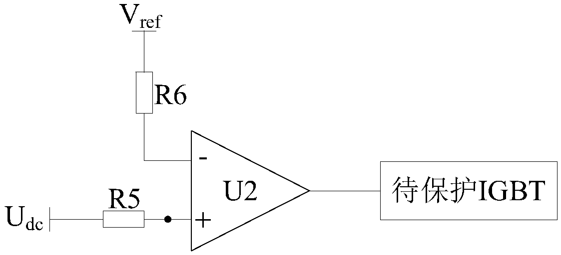
[0060] figure 1 It is the structural diagram of the IGBT protection circuit module of Embodiment 1, such as figure 1 As shown, the IGBT protection circuit of Embodiment 1 includes an adder module 100 and a comparator module 101;
[0061] The input terminal of the adder module 100 is used to access the DC bus voltage U dc and the output current I of the IGBT to be protected c , the adder module 100 is used to calculate the DC bus voltage U dc and output current I c Implement the addition operation;
[0062] Among them, the DC bus voltage U dc That is, the DC bus voltage of the inverter circuit applying the IGBT to be protected, the output current I c is the current flowing through the IGBT to be protected. Among them, the output current I c After inputting into the adder module, according to the characteristics of the input interface of the adder module, the output current I c Converted to the corresponding correction voltage. To the DC bus voltage U dc and output cu...
Embodiment 2
[0090] An embodiment of the present invention also provides a three-phase inverter, including an IGBT protection circuit, a first IGBT, a second IGBT, a third IGBT, a fourth IGBT, a fifth IGBT, and a sixth IGBT;
[0091] The emitter of the first IGBT is connected to the collector of the second IGBT, and the collector of the first IGBT and the emitter of the second IGBT are used to connect the DC bus voltage U dc ;
[0092] The emitter of the third IGBT is connected to the collector of the fourth IGBT, and the collector of the third IGBT and the emitter of the fourth IGBT are used to access the DC bus voltage U dc ;
[0093] The emitter of the fifth IGBT is connected to the collector of the sixth IGBT, and the gap between the collector of the fifth IGBT and the emitter of the sixth IGBT is used to access the DC bus voltage U dc ;
[0094] The IGBT protection circuit includes an adder module and a comparator module;
[0095] The input terminal of the adder module is used to ...
Embodiment 3
[0100] Figure 5 It is the flow chart of the IGBT protection method of embodiment three, such as Figure 5 As shown, the IGBT protection method of the third embodiment includes steps S100 to S102:
[0101] S100, get the DC bus voltage U dc and the output current I of the IGBT to be protected c ;
[0102] S101, according to the output current I c The product of the preset resistance value is obtained to obtain the corrected voltage;
[0103] Wherein, the magnitude of the correction voltage can be adjusted by adjusting the preset resistance value. The smaller the preset resistance value, the higher the output capability of the IGBT to be protected. Wherein, the preset resistance value may correspond to the type of the IGBT to be protected.
[0104] S102, if the DC bus voltage U dc and the sum of the correction voltage is greater than the reference voltage V ref , turn off the IGBT to be protected.
[0105] After obtaining the corrected voltage, calculate the DC bus vol...
PUM
 Abstract
Description
Claims
Application Information
 - R&D
- Intellectual Property
- Life Sciences
- Materials
- Tech Scout
- Unparalleled Data Quality
- Higher Quality Content
- 60% Fewer Hallucinations
Browse by: Latest US Patents, China's latest patents, Technical Efficacy Thesaurus, Application Domain, Technology Topic, Popular Technical Reports.
© 2025 PatSnap. All rights reserved.Legal|Privacy policy|Modern Slavery Act Transparency Statement|Sitemap|About US| Contact US: help@patsnap.com


