
Electric leakage protection circuit, electric leakage protection device and electric equipment

A leakage protection and circuit technology, which is applied in the direction of emergency protection circuit devices, circuit devices, emergency protection devices with automatic disconnection, etc., can solve the problems of difficult matching and complicated manufacturing processes of silicon controlled rectifiers, and achieve the convenience of full integration, The effect of saving SCR

Active Publication Date: 2020-06-26
WUXI CRYSTAL SOURCE MICROELECTRONICS CO LTD
View PDF6 Cites 0 Cited by
  • Summary
  • Abstract
  • Description
  • Claims
  • Application Information

AI Technical Summary

Problems solved by technology

Because the manufacturing process of thyristor is difficult to match with the current integrated circuit manufacturing process or the manufacturing process becomes complicated

Method used


Image

  • Electric leakage protection circuit, electric leakage protection device and electric equipment

Examples


Embodiment 1

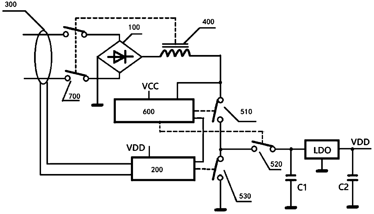
[0030] see figure 1 , figure 1 A connection schematic diagram of a leakage protection circuit provided by an embodiment of the present invention, the leakage protection circuit includes a rectifier bridge stack 100, a leakage detection unit 200, a leakage induction coil 300, a solenoid 400, a first switch 510, and a second switch 520 , the third switch 530, the decoupling control unit 600 and the decoupling switch 700;

[0031] Wherein, the output end of the leakage induction coil 300 is connected to the rectifier bridge stack 100, the output end of the rectifier bridge stack 100 is connected to the solenoid 400, and the output end of the solenoid 400 is connected to the first switch 510 and the decoupling control unit 600;

[0032] The leakage induction coil 300 is grounded after being connected in series with the first switch 510 and the third switch 530 through the decoupling switch 700, and the first switch 510 and the third switch 530 are also connected to the second swi...

Embodiment 2

[0051] A leakage protection device in this embodiment includes the leakage protection circuit described in the first embodiment above. The connection mode and working principle of the specific circuits involved in the leakage protection device in this embodiment are consistent with those in the first embodiment. This will not be repeated here.

Embodiment 3

[0053] This embodiment provides an electrical device, which includes the leakage protection circuit described in Embodiment 1. The circuit connection mode and working principle of the leakage protection circuit are consistent with Embodiment 1, and will not be repeated here.

[0054] Beneficial effects of the present invention:


PUM


Abstract

The invention relates to an electric leakage protection circuit, an electric leakage protection device and electric equipment. The electric leakage protection circuit comprises an electric leakage detection unit, an electric leakage induction coil, a first switch, a second switch, a third switch, an unhooking control unit, a capacitor and an unhooking switch; the electric leakage induction coil isconnected with the first switch and the third switch in series through the unhooking switch and then grounded, and the first switch and the third switch are further connected with the second switch and grounded through the capacitor. The electric leakage detection unit is connected with the electric leakage induction coil and the unhooking control unit. When the electric leakage detection unit detects electric leakage, the unhooking control unit controls the first switch and the third switch to be switched on at the same time, and the unhooking switch is switched off. According to the invention, an electric leakage protection function can be realized, an electric leakage protection circuit, an electric leakage protection device and silicon controlled rectifiers in electric equipment are saved, and the whole circuit can be conveniently and completely integrated.

Description

technical field [0001] The invention belongs to the technical field of power supply, and in particular relates to a leakage protection circuit, a leakage protection device and electrical equipment. Background technique [0002] In an AC power supply system, a leakage protection device is required, and the leakage protection device has the function of personal safety protection for users. [0003] Therefore, the electric power department mandates that electric units or families must install leakage protection devices, and the plugs and power sockets of some household appliances are also equipped with leakage protection devices. In this way, the quantity of leakage protective devices used in our country and even in the whole world is huge. [0004] The leakage protection device uses an integrated circuit to detect leakage, and uses the conduction of the thyristor to force the solenoid to have a current flow, causing the decoupling switch of the solenoid to be disconnected. B...

Claims


Application Information

Patent Timeline
Patent Type & Authority Applications(China)
IPC IPC(8): H02H3/00H02H1/06
CPCH02H3/00H02H1/06
Inventor 雍广虎
Owner WUXI CRYSTAL SOURCE MICROELECTRONICS CO LTD
Learn More