
Air draft heat dissipation type electric power cabinet

A heat-dissipating, power cabinet technology, applied in the direction of electrical components, substation/power distribution device shell, substation/switch layout details, etc., can solve problems such as difficulty in heat dissipation, poor air flow, etc., to reduce service life, increase gas flow rate, The effect of reducing air pressure

Inactive Publication Date: 2020-06-26
胡从勇
View PDF4 Cites 8 Cited by
  • Summary
  • Abstract
  • Description
  • Claims
  • Application Information

AI Technical Summary

Problems solved by technology

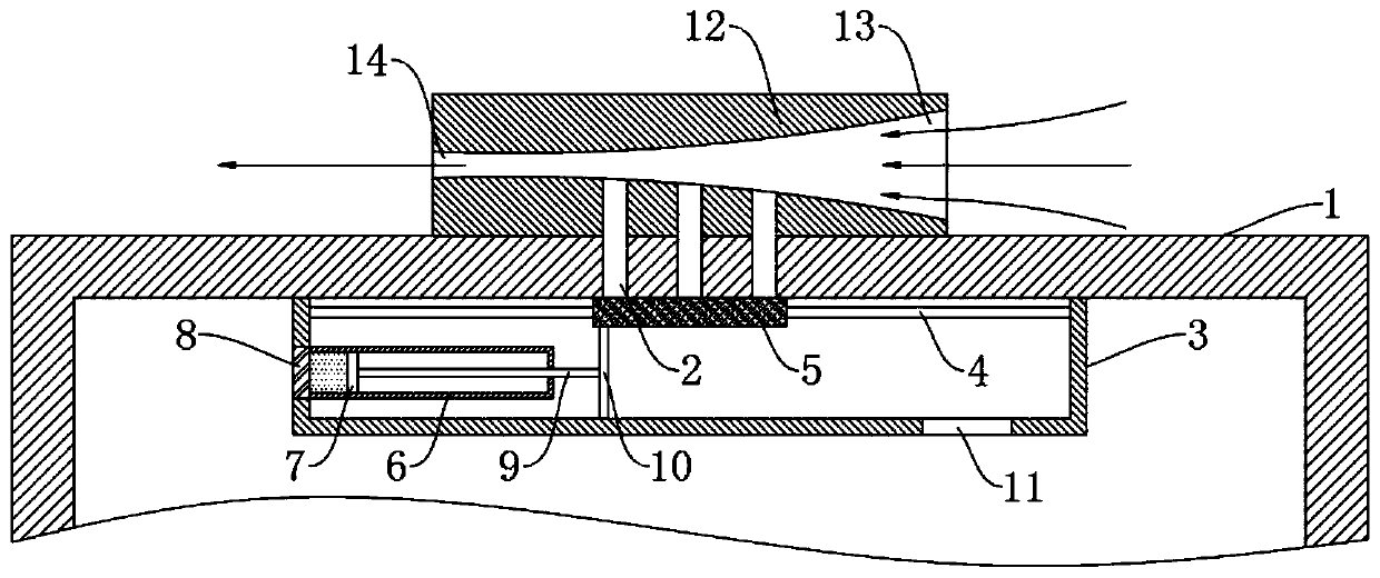
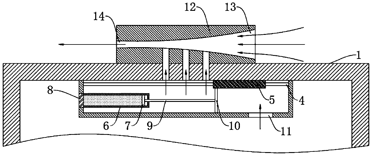
[0004] The object of the present invention is to solve the shortcomings in the prior art, and propose a kind of ventilation and heat dissipation power cabinet, which is provided with a heat dissipation platform, an air inlet, an air outlet, a heat dissipation hole and a pushing mechanism, when the heat in the cabinet is too much When the temperature is high, the connecting rod pushes the sealing plate to slide, so that it no longer seals the heat dissipation hole, and the inside of the cabinet is connected with the airflow channel, which utilizes the characteristics of poor gas fluidity inside the cabinet and good air fluidity outside the cabinet, through two The pressure difference between the cabinet and the cabinet can be realized by drawing air to dissipate heat, which effectively solves the problem of poor air flow in the power cabinet in the traditional technology due to rain shelter and anti-theft, which makes it difficult to dissipate heat.

Method used


Image

  • Air draft heat dissipation type electric power cabinet
  • Air draft heat dissipation type electric power cabinet
  • Air draft heat dissipation type electric power cabinet

Examples


Embodiment 1

[0020] refer to Figure 1-2 , a kind of ventilation and heat dissipation power cabinet, comprising a cabinet body 1, the upper end of the cabinet body 1 is fixedly connected with a cooling table 12, one end of the cooling table 12 is provided with an air inlet 13, and the other end of the cooling table 12 is provided with an air outlet 14, and the air inlet The tuyere 13 and the air outlet 14 communicate with each other through the airflow passage, and the upper end of the cabinet body 1 is located at the position directly below the heat dissipation table 12. There are heat dissipation holes 2, and the heat dissipation holes 2 communicate with the airflow passage.

[0021] It should be noted that the diameter of the air inlet 13 is greater than the diameter of the air outlet 14, so when the airflow flows from the air inlet 13 to the air outlet 14, that is, when the airflow is in the airflow channel, its flow speed will increase significantly. According to fluid mechanics: "flui...

Embodiment 2

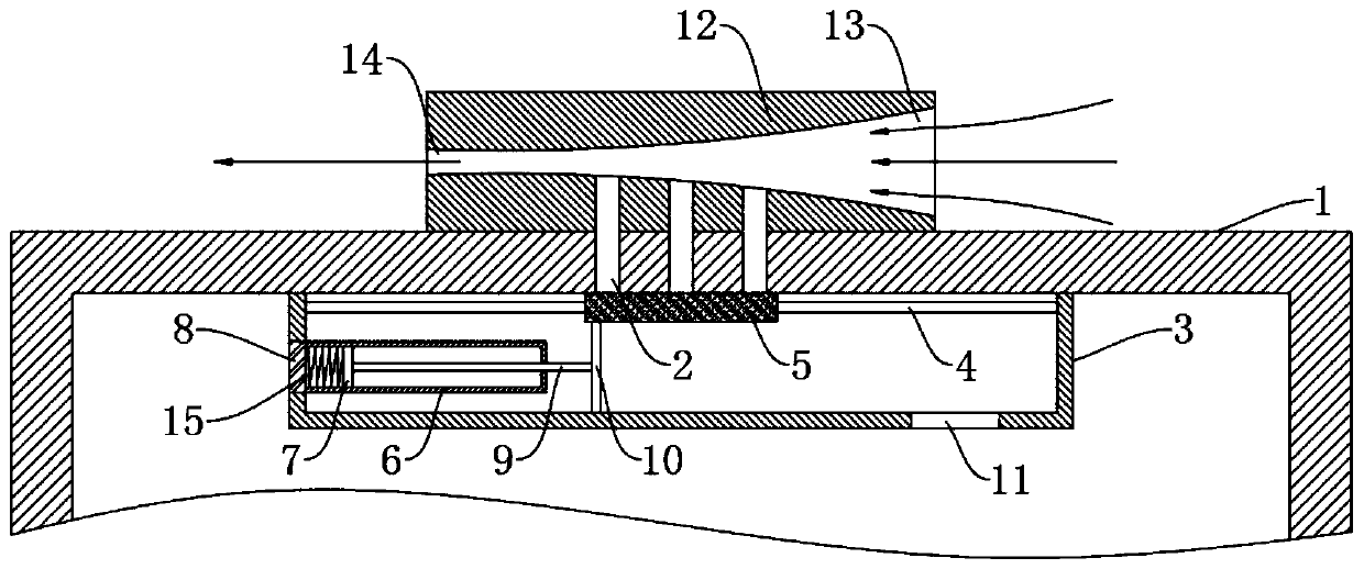
[0030] refer to image 3 , and the difference from Embodiment 1 is that: the thermally deformable metal 15 is fixedly connected between the heat conduction plate 8 and the slider 7, and the cavity between the inner wall of the slider cylinder 6 and the slider 7 is not filled with evaporating liquid.

[0031] It should be noted that the above-mentioned thermally deformable metal 15 adopts a two-way memory alloy, which is compressed into a folded shape at room temperature, and its minimum transformation temperature under hot air is 40°C, and nickel-titanium alloy or Cu can be used. - Zn-Al alloy. When the heat-deformed metal reaches the lowest transformation temperature, it will return to a straight strip, and when it is cooled below the transformation temperature, it can automatically change into a folded shape, and this process can be repeated.

[0032] In this embodiment, the heat-deformable metal 15 elongates when a high temperature is generated in the cabinet, thereby push...


PUM


Abstract

The invention discloses an air draft heat dissipation type electric power cabinet. The cabinet comprises a cabinet body, a heat dissipation table is fixedly connected to the upper end of the cabinet body, an air inlet is formed in one end of the heat dissipation table, an air outlet is formed in the other end of the heat dissipation table, the air inlet and the air outlet are communicated throughan airflow channel, and heat dissipation holes are formed in the positions, located under the heat dissipation table, of the upper end of the cabinet body. The heat dissipation table, the air inlet, the air outlet, the heat dissipation holes and the pushing mechanism are arranged; when the heat in the cabinet body is too much and the temperature is high; connecting rod pushing sealing plate to slide, the heat dissipation holes are not sealed any more; the interior of the cabinet body communicates with the airflow channel; by utilizing the characteristics of poor air fluidity in the cabinet body and good air fluidity outside the cabinet body, air draft type heat dissipation in the cabinet body is realized through the pressure difference between the air fluidity in the cabinet body and the air fluidity outside the cabinet body, and the problem that the power cabinet is difficult to dissipate heat due to poor air fluidity in the power cabinet caused by rain sheltering and theft preventionin the prior art is effectively solved.

Description

technical field [0001] The invention relates to the technical field of electric equipment, in particular to a draft and heat dissipation type power cabinet. Background technique [0002] The power cabinet is one of the most common and important equipment in the field of basic power facilities. Its function lies in the installation of circuits and power components. There are a large number of complex power components installed inside the power cabinet. Therefore, when the power distribution cabinet The electrical components in the cabinet are in a high-load working state, which will generate a lot of heat. If the heat is not dissipated in time, it will cause damage to the electrical components in the cabinet. [0003] However, due to reasons such as rain shelter, sealing, and anti-theft of the power cabinet, the air in it is often difficult to circulate, which leads to the fact that the heat inside is difficult to exchange with the outside heat under the high load of power co...

Claims


Application Information

Patent Timeline
Patent Type & Authority Applications(China)
IPC IPC(8): H02B1/56H02B1/28H02B1/30H02B1/26
CPCH02B1/26H02B1/28H02B1/30H02B1/306H02B1/565
Inventor 胡从勇
Owner 胡从勇
Learn More