
Mobile robot positioning method based on visual guidance laser repositioning

A technology of mobile robot and positioning method, which is applied in the directions of instruments, electromagnetic wave re-radiation and utilization of re-radiation, etc. It can solve the problems of difficult error recovery, difficult initialization, easy loss of positioning, etc., and achieves stable and reliable positioning, rich positioning information, and positioning stable effect

Active Publication Date: 2020-06-26
TONGJI UNIV
View PDF15 Cites 12 Cited by
  • Summary
  • Abstract
  • Description
  • Claims
  • Application Information

AI Technical Summary

Problems solved by technology

LiDAR-based methods can maintain good positioning in structured environments and are insensitive to high-speed motion, but they are difficult to initialize and error recovery is difficult
The current unmanned transport vehicles based on laser positioning technology often need fixed stations, initialize at the set stations and cannot flexibly start work anywhere
In addition, once its positioning occurs, due to the symmetry and similarity of the factory environment structure, it often takes a long time to update and restore to the correct position, which greatly affects production efficiency and is more likely to cause safety hazards
The vision-based positioning method can be quickly initialized, but it cannot cope with fast movement and rotation, and has high requirements on environmental features and light. If the environmental features cannot be maintained all the time, it is easy to lose the positioning

Method used


Image

  • Mobile robot positioning method based on visual guidance laser repositioning
  • Mobile robot positioning method based on visual guidance laser repositioning
  • Mobile robot positioning method based on visual guidance laser repositioning

Examples


Embodiment Construction

[0049] The present invention will be described in detail below in conjunction with the accompanying drawings and specific embodiments. This embodiment is carried out on the premise of the technical solution of the present invention, and detailed implementation and specific operation process are given, but the protection scope of the present invention is not limited to the following embodiments.

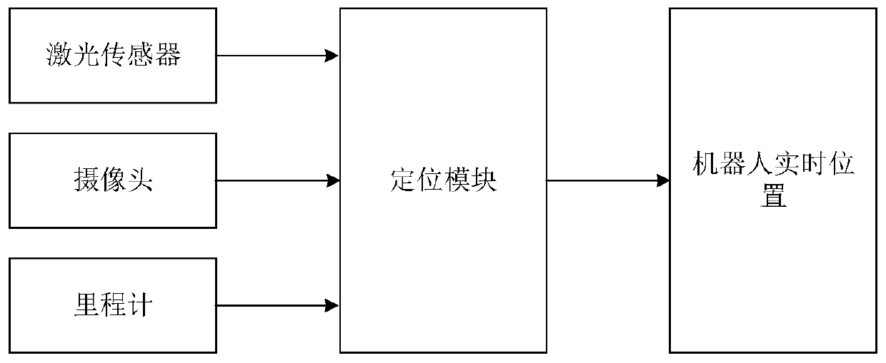
[0050] like figure 1 As shown, the positioning system adopted by the robot in this embodiment includes a laser sensor, a camera, and an odometer, and a positioning module respectively connected to the laser sensor, the camera, and the odometer. The mobile robot positioning method based on vision-guided laser relocation is implemented in the positioning module to output the position of the robot in real time.

[0051] like Figure 5As shown, the robot is equipped with a camera, lidar and wheel odometry. Define the world coordinate system as the coordinate system used when building l...


PUM


Abstract

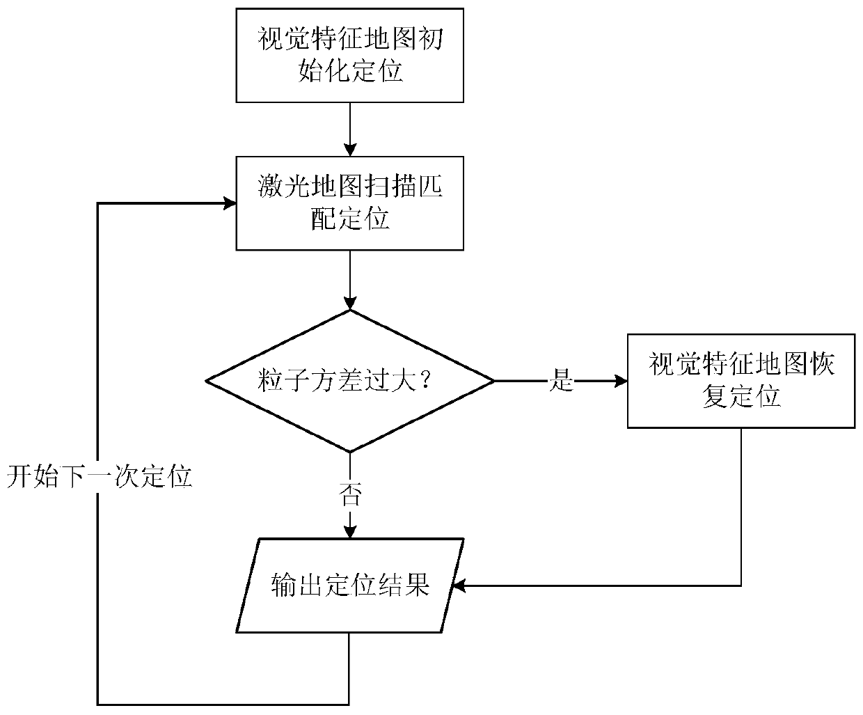
The invention relates to a mobile robot positioning method based on visual guidance laser repositioning, and the method comprises the following steps: carrying out the initialization positioning of the position of a robot according to a visual feature map, and mapping the position of the robot to a laser map; adopting an adaptive particle filtering method, and obtaining accurate positioning of therobot on a laser map according to a laser scanning matching result; judging whether the particle variance positioned in the positioning process of the self-adaptive particle filtering method exceedsa set threshold value or not: if so, performing visual repositioning by utilizing a visual feature map, outputting a positioning result of the robot, and re-initializing the current particle, namely,performing error recovery; if not, outputting a positioning result of the robot. Compared with the prior art, the method has the advantages that the robot can quickly recover accurate positioning by means of the repositioning function of the visual feature map during initialization or after being bound, so the stability and reliability of positioning are guaranteed.

Description

technical field [0001] The invention relates to the field of autonomous positioning of mobile robots, in particular to a positioning method for mobile robots based on vision-guided laser repositioning. Background technique [0002] Positioning technology is the basis for robots to move autonomously, and is the key to endow robots with perception and action capabilities. With the development and wide application of robot technology, more and more industrial handling robots and inspection robots need to work in unmanned factories, and positioning technology is the basis for their task execution. [0003] In the traditional positioning method, absolute positioning mainly uses navigation beacons, signs and satellite navigation technology for positioning, but the construction and maintenance costs of beacons are relatively high, and GPS can only be used outdoors. Relative positioning mainly uses wheel encoders, inertial measurement units and laser radars. Both wheel encoders and...

Claims


Application Information

Patent Timeline
IPC IPC(8): G01S17/88G01S17/66G01S17/06
CPCG01S17/88G01S17/66G01S17/06
Inventor 刘成菊陈浩陈启军
Owner TONGJI UNIV
Learn More