Automatic variable control surface speed reducing mechanism with feedback for pneumatic test

A technology of wind test and deceleration mechanism, which is applied in the field of aerospace aerodynamics, can solve the problems of consuming resources and time, achieve the effect of ensuring the accuracy of angle adjustment and eliminating motion jamming

Inactive Publication Date: 2020-06-26
珠海伺动科技有限公司
View PDF9 Cites 0 Cited by
  • Summary
  • Abstract
  • Description
  • Claims
  • Application Information

AI Technical Summary

Problems solved by technology

Some aerodynamic tests are carried out in a sealed cabin. Every time an angle is changed, workers need to release the pressure before entering the test cabin to operate the wing angle. After adjustment, they need to re-press. The process is very resource-intensive and time-consuming, so it is urgent An automatic variable rudder mechanism is needed to automatically adjust the wing angle, and the automatic variable rudder mechanism realizes the conversion of the high speed and low torque of the motor in the variable rudder steering gear to the low speed and high torque within the limited space of wing thickness. Difficulties that urgently need to be overcome

Method used


Image

  • Automatic variable control surface speed reducing mechanism with feedback for pneumatic test
  • Automatic variable control surface speed reducing mechanism with feedback for pneumatic test
  • Automatic variable control surface speed reducing mechanism with feedback for pneumatic test

Examples


Embodiment Construction

[0024] The present invention will be described in detail below with reference to the accompanying drawings and examples.

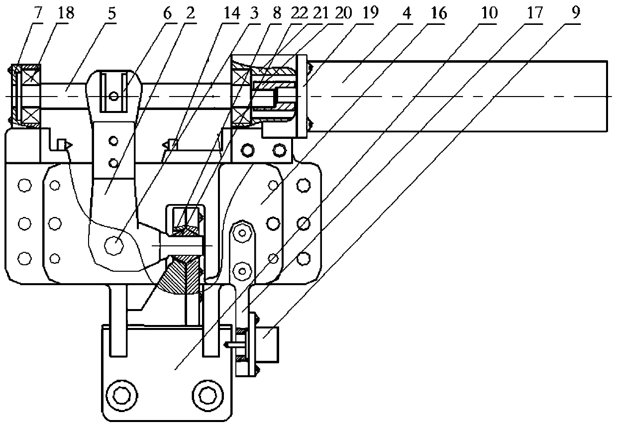
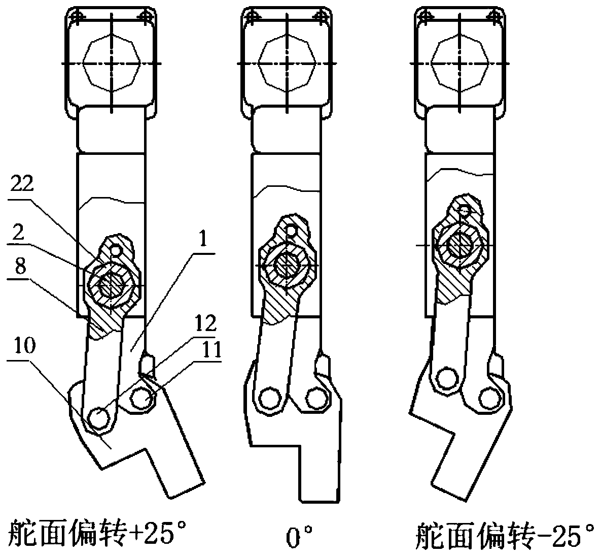
[0025] as attached figure 1 and 2 As shown, the present invention provides an automatic rudder surface deceleration mechanism with feedback for aerodynamic tests, the mechanism includes a left support 1, a right support 15, a motor 4, a cover plate 16, a shift fork 2, a nut 6, and a screw rod 5. Spherical push rod 8, ball head 22 and rudder surface mounting seat 10;

[0026] The screw mandrel 5 and the motor 4 are designed separately. The two ends of the screw mandrel 5 are supported on the left support 1 and the right support 15 through the bearing 18. The motor 4 on the support 15 is connected with the screw mandrel 5 through a coupling 20 . The motor 4 drives the screw mandrel 5 to rotate coaxially after being decelerated by the gear box reducer. The two cover plates 16 respectively form an installation cavity through up and down on the front and re...


PUM


Abstract

The invention discloses an automatic control surface changing speed reducing mechanism with feedback for a pneumatic test. Two cover plates in the mechanism respectively form a mounting cavity which is through up and down on the front and rear surfaces of the left and right supports; a shifting fork is mounted in the cavity through a rotating shaft; the upper end of the shifting fork is matched with a nut on a screw rod; the tail end of the shifting fork is matched with a ball socket of a spherical push rod through a ball head, the lower end of the spherical push rod is connected with a control surface mounting base through a movable shaft, the control surface mounting base is movably connected to the lower ends of the left support and the right support through a fixed shaft, and the center of the ball head is located between the center of the movable shaft and the center of the fixed shaft. A motor drives the screw rod to rotate forwardly and reversely, the nut linearly moves along the screw rod and drives the shifting fork to rotate forwardly and reversely around the rotating shaft, the lower end of the shifting fork drives the spherical push rod to push and pull the control surface mounting base, and the control surface mounting base angularly deflects around the fixed shaft. According to the invention, the conversion from high rotating speed and low torque to low rotating speed and high torque of the motor in a variable-control-surface steering engine can be realized in a limited space.

Description

technical field [0001] The invention relates to an automatic variable rudder surface deceleration mechanism with feedback for aerodynamic tests, which belongs to the technical field of aerospace aerodynamics. Background technique [0002] The wind tunnel test is based on the principle of relativity of motion. The model or object of the aircraft is fixed in the artificial environment on the ground, and the air flow is artificially created to simulate various complex flight states in the air to obtain test data. [0003] During the wind tunnel test, the model wing needs to stay at different angles for a certain period of time according to the set procedure to carry out the blowing test. Most of the existing pneumatic test rooms are manually operated by workers, and the efficiency is low. Some aerodynamic tests are carried out in a sealed cabin. Every time an angle is changed, workers need to release the pressure before entering the test cabin to operate the wing angle. After ...

Claims


Application Information

Patent Timeline
Patent Type & Authority Applications(China)
IPC IPC(8): G01M9/04B64F5/60
CPCB64F5/60G01M9/04
Inventor 孙立伟杨春秋崔文昊姚晓先
Owner 珠海伺动科技有限公司
Why Eureka
Try Eureka