
Flue gas condensing tube and gas heater

A flue gas condensing and condensing tube technology, applied in steam/steam condensers, air heaters, fluid heaters, etc., can solve the problems of low utilization rate of gas calorific value, insufficient combustion of gas, low heat exchange efficiency, etc. Achieve the effect of high heat recovery efficiency of flue gas, increase thermal power, and high utilization rate of calorific value

Pending Publication Date: 2020-06-26
无锡华澳科技有限公司
View PDF0 Cites 0 Cited by
  • Summary
  • Abstract
  • Description
  • Claims
  • Application Information

AI Technical Summary

Problems solved by technology

In the prior art, the flue gas condenser has the following problems: After the flue gas condenser cools down to below 100°C, the condensed water generated will flow back to extinguish the flame or accumulate in the pipe to affect the heat transfer effect; the heat transfer efficiency is low A large amount of heat is taken away by the flue gas and wasted; the gas is not fully burned, resulting in the generation of carbon monoxide and low utilization of the calorific value of the gas

Method used


Image

  • Flue gas condensing tube and gas heater
  • Flue gas condensing tube and gas heater
  • Flue gas condensing tube and gas heater

Examples


Embodiment Construction

[0025] The following will clearly and completely describe the technical solutions in the embodiments of the present invention with reference to the accompanying drawings in the embodiments of the present invention. Obviously, the described embodiments are only some, not all, embodiments of the present invention. Based on the embodiments of the present invention, all other embodiments obtained by persons of ordinary skill in the art without creative efforts fall within the protection scope of the present invention.

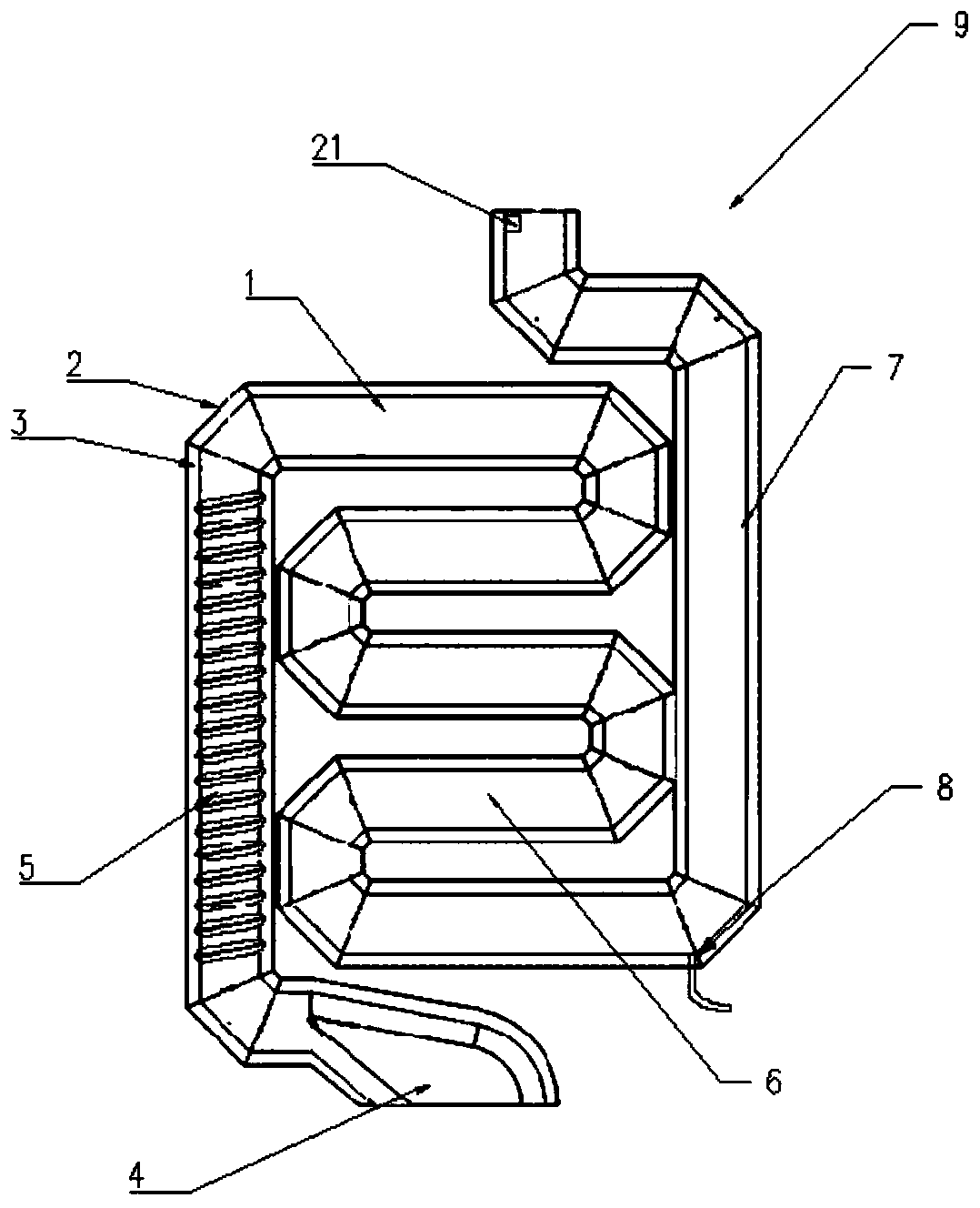
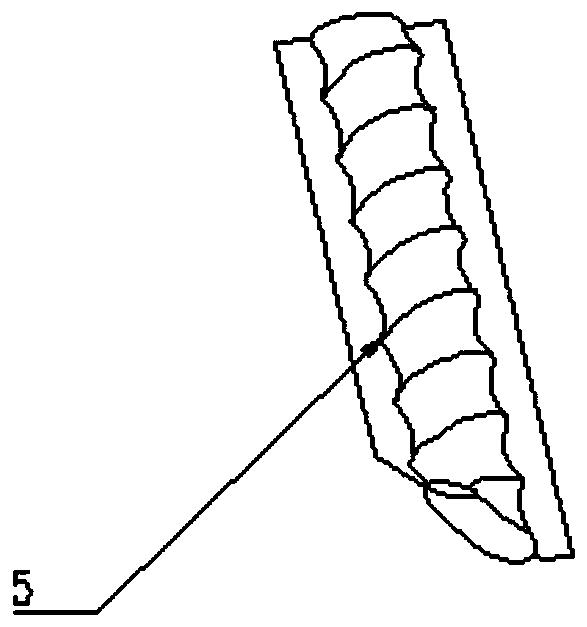
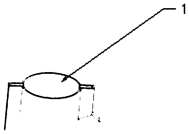
[0026] In a specific embodiment of the present invention, a flue gas condensation pipe 9, such as figure 1 , figure 2 , image 3 , Figure 5 and Figure 7 As shown, it includes: a fire pipe 1 and a water tank 2; wherein, the fire tube 1 is arranged inside the water tank 2, and a liquid cavity 3 is formed between the water tank 2 and the fire tube 1; the fire tube 1 includes smoke inlets 4 arranged in sequence , high-temperature section condensation pipe 5, low...


PUM


Abstract

The invention provides a flue gas condensing tube and a gas heater, which are used for solving the technical problems that condensed water of a gas heating device in the prior art is accumulated in apipeline or extinguishes flame, a gas heat value utilization rate is low, and a flue gas heat recovery rate is low. The flue gas condensing tube comprises a water container and a fire tube. The gas heater comprises the flue gas condensing tube, a housing, a condensed water inlet, a condensed water outlet, a combustion chamber, a gas tube, a condensed water exhaust device, an exhaust fan, a controller, a condensed water guide-out device and a power supply. With the adoption of the technical scheme adopted by the invention, a high-temperature section condensing tube and a low-temperature sectioncondensing tube are arranged, so that flue gas is prevented from forming condensed water in the high-temperature section condensing tube to extinguish the flame; the low-temperature section condensing tube adopts an S-shaped tube, and is relatively long, so that flue gas recovery efficiency is high, and thermal power of the heater is effectively improved; a bottom condensed water drainage deviceis arranged to exhaust condensed water in real time; and gas is sufficiently combusted through a reasonable excess air coefficient, so that gas is sufficiently combusted, and carbon monoxide is prevented from being generated while the heat value utilization rate is high.

Description

technical field [0001] The invention relates to the field of heating equipment, in particular to a flue gas condensation pipe and a gas heater. Background technique [0002] Heating equipment is widely used in the fields of domestic heating and industrial heating, among which gas heating furnaces are commonly used. Gas heating furnaces are mainly divided into two types, one is to directly use gas to heat hot water, and the other is to transfer heat to hot water in the condensation pipe through the flue gas generated by combustion. In the prior art, the flue gas condenser has the following problems: After the flue gas condenser cools down to below 100°C, the condensed water generated will flow back to extinguish the flame or accumulate in the pipe to affect the heat transfer effect; the heat transfer efficiency is low As a result, a large amount of heat is taken away by the flue gas and wasted; the gas is not fully burned, resulting in the generation of carbon monoxide and l...

Claims


Application Information

Patent Timeline
Patent Type & Authority Applications(China)
IPC IPC(8): F24H8/00F24H9/00F24H9/12F24H9/16F24H9/20F28B1/02F28B9/08F28B11/00
CPCF24H8/006F24H9/0036F24H9/0031F24H9/2035F24H9/16F28B1/02F28B9/08F28B11/00F24H9/13Y02B30/00
Inventor 朱延涛徐伟徐亮吴椿
Owner 无锡华澳科技有限公司
Learn More