
Gate valve with high sealing performance

A high-sealing, gate valve technology, applied in shaft seals, sliding valves, valve details, etc., can solve problems that affect the sealing performance of gate valves, difficult to open and close gate valves, and loss of sealing rings, and achieve the effect of avoiding failure

Inactive Publication Date: 2020-06-26
HUBEI TAIHE PETROCHEM EQUIP
View PDF0 Cites 0 Cited by
  • Summary
  • Abstract
  • Description
  • Claims
  • Application Information

AI Technical Summary

Problems solved by technology

[0003] During the use of the gate valve, it is usually necessary for the operator to judge whether the gate valve is fully opened or closed. If the operation is large, it is easy to cause the valve stem to move up or down excessively. In the subsequent opening and closing process of the gate valve, especially large It will be difficult for the gate valve to open and close the gate valve. In addition, the long-term friction between the valve plate and the sealing ring of the gate valve will cause the loss of the sealing ring and affect the sealing performance of the gate valve.

Method used


Image

  • Gate valve with high sealing performance
  • Gate valve with high sealing performance
  • Gate valve with high sealing performance

Examples


Embodiment Construction

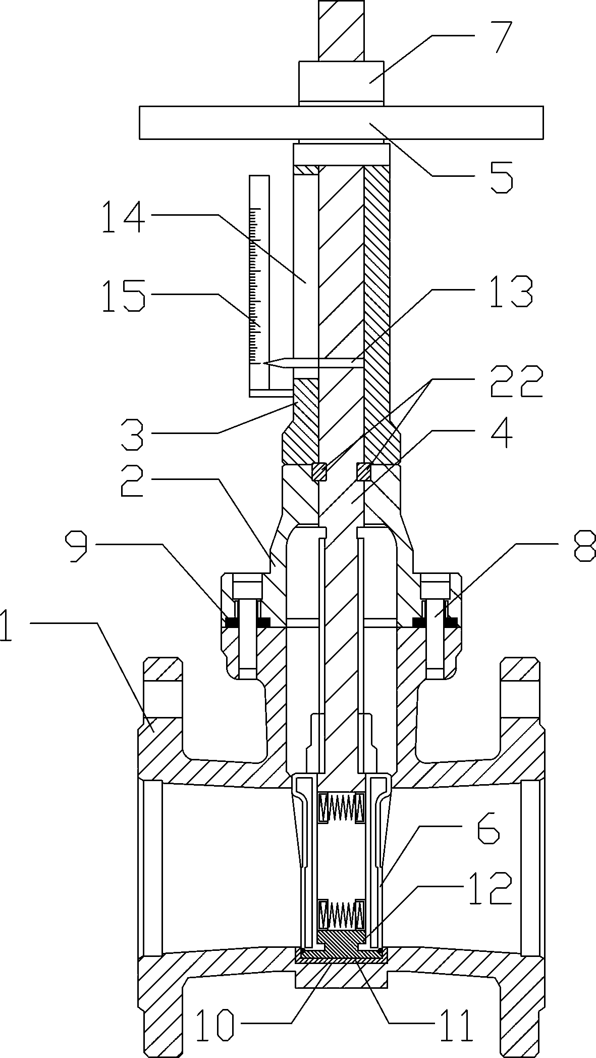
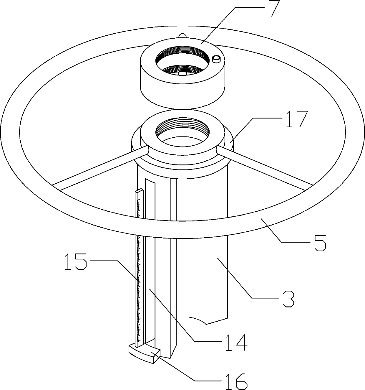
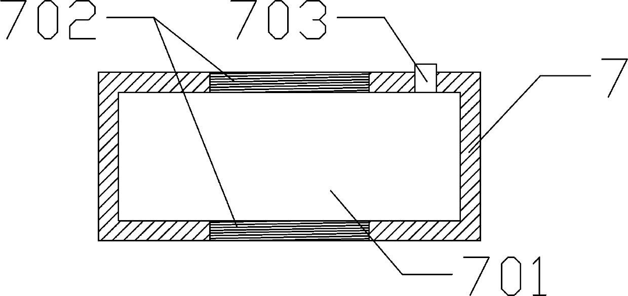
[0029] Such as Figure 1-6 Among them, a high-sealing gate valve includes a valve body 1, a valve cover 2 is arranged above the valve body 1, a bracket 3 is arranged above the valve cover 2, a handwheel 5 is arranged above the bracket 3, and the upper end of the valve stem 4 is connected with the handwheel 5. The lower end of the valve stem 4 passes through the bracket 3 and the bonnet 2 and then extends into the valve body 1. The lower end of the valve stem 4 in the valve body 1 is provided with a valve plate 6. On one side of the bracket 3 A strip-shaped through hole 14 is provided, an annular groove 401 is provided on a section of the valve stem 4 in the bracket 3, a pointer 13 is provided on the annular groove 401, and a support is provided on one side of the bracket 3 with the strip-shaped through hole 14. Block 16, the support block 16 is fixedly provided with a vertical scale rod 15, and one end of the pointer 13 passes through the bar-shaped through hole 14 and contact...


PUM


Abstract

The invention discloses a gate valve with the high sealing performance. The gate valve with the high sealing performance comprises a valve body, a valve deck is arranged above the valve body, a support is arranged above the valve deck, a hand wheel is arranged above the support, the lower end of a valve rod extends into the valve body, valve plates are arranged at the lower end of the valve rod, astrip-shaped through hole is formed in one side of the support, an annular groove is formed in one section, located in the support, of the valve rod, a pointer is arranged on the annular groove, a vertical scale rod is arranged on the side, provided with the strip-shaped through hole, of the support, one end of the pointer penetrates through the strip-shaped through hole and is in contact with the scale rod, the lower end of the valve rod is a T-shaped end, the number of the valve plates is two, the T-shaped end is fixed at the upper part of an area between the two valve plates, an I-shaped block is arranged at the lower part of the area between the two valve plates, and springs are arranged in the area between the two valve plates. By the adoption of the structure, the gate valve can beopened and closed more easily, the opening degree of the gate valve can be visually obtained and determined, tight abutting of the valve plates and the valve rod caused by excessive opening and closing of the gate valve is avoided, self-adaptive adjustment can be achieved according to the loss degree of a sealing layer, and the sealing performance of the gate valve is guaranteed.

Description

technical field [0001] The invention relates to the field of valves, in particular to a gate valve with high sealing performance. Background technique [0002] The gate valve is a gate of the opening and closing part. The direction of movement of the gate is perpendicular to the direction of the fluid. The gate valve can only be fully opened and fully closed. When the gate valve is closed, the sealing surface can be sealed only by the medium pressure, that is, only by the medium pressure to press the sealing surface of the gate plate to the valve seat on the other side to ensure the sealing of the sealing surface, which is self-sealing. Most of the gate valve is forced seal, that is to say, when the valve is closed, the gate should be pressed to the valve seat by external force, so as to ensure the sealing surface sealing. Movement mode: The gate of the gate valve moves in a straight line with the valve stem. [0003] During the use of the gate valve, it is usually necessa...

Claims


Application Information

Patent Timeline
Patent Type & Authority Applications(China)
IPC IPC(8): F16K3/16F16K3/30F16K27/04F16K31/60F16K41/02
CPCF16K3/16F16K3/30F16K27/044F16K31/60F16K41/02
Inventor 王晶秋章文忠
Owner HUBEI TAIHE PETROCHEM EQUIP
Learn More