Eureka AIR delivers breakthrough ideas for toughest innovation challenges, trusted by R&D personnel around the world.

Mold slide device

A positioning and mold technology, which is applied in the field of mold positioning devices, can solve the problems such as the retreat of the positioning inserts, the excessive glue in the product, and the protruding edge.

Inactive Publication Date: 2020-06-26
GUANGDONG EVERWIN PRECISION TECH
View PDF6 Cites 0 Cited by
  • Summary
  • Abstract
  • Description
  • Claims
  • Application Information

AI Technical Summary

Problems solved by technology

[0003] When the mold cannot be designed with a shovel, or directly use the hydraulic cylinder to pull the core, the row insert cannot be locked by the mold clamping force, and usually can only be locked by the force of the hydraulic cylinder
Due to the inaccuracy of the hydraulic cylinder, the row inserts often retreat under the action of the injection pressure, resulting in problems such as excess glue, burrs, and flashes on the product.

Method used


Image

  • Mold slide device
  • Mold slide device
  • Mold slide device

Examples


Embodiment Construction

[0034] In order to facilitate the understanding of the present invention, the present invention will be described more fully below with reference to the associated drawings. Preferred embodiments of the invention are shown in the accompanying drawings. However, the present invention can be embodied in many different forms and is not limited to the embodiments described herein. On the contrary, these embodiments are provided to make the understanding of the disclosure of the present invention more thorough and comprehensive.

[0035] It should be noted that when an element is referred to as being “fixed” to another element, it can be directly on the other element or there can also be an intervening element. When an element is referred to as being "connected to" another element, it can be directly connected to the other element or intervening elements may also be present.

[0036] Unless otherwise defined, all technical and scientific terms used herein have the same meaning as...


PUM


Abstract

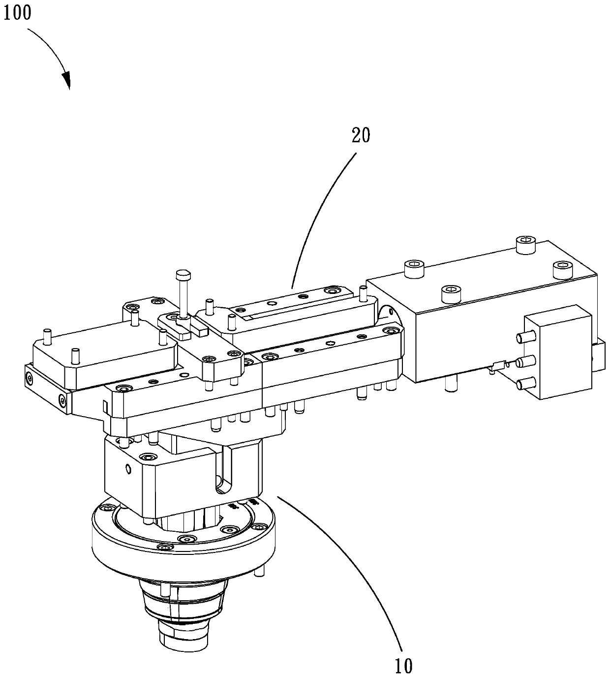
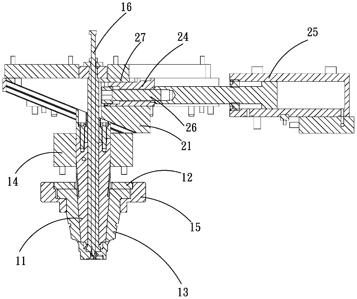
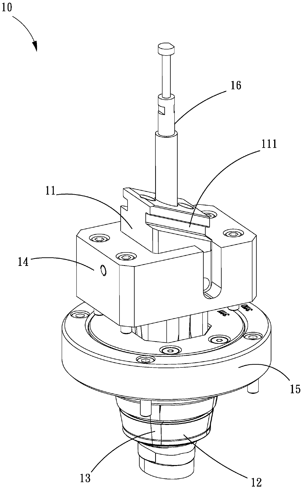
The invention relates to a mold slide device. The mold slide device comprises a slide assembly and a driving assembly, wherein the slide assembly comprises a slide driving block, a mounting seat and aslide insert; the slide insert abuts against the slide driving block and acts along with movement of the slide driving block; the driving assembly comprises a sliding inclined wedge, a guide rail, ananti-backward pin, a push block and a driver; the sliding direction of the sliding inclined wedge is perpendicular to the sliding direction of the slide driving block; a clamping groove allowing theanti-backward pin to be inserted therein is formed in the inner side of the guide rail; the sliding inclined wedge is provided with a sliding groove slidably connected with the push block; a recedingpart and an abutting part are arranged on the outer side of the push block; and the anti-backward pin abuts against the outer side of the push block. According to the mold slide device, the driving assembly with an anti-backward structure is utilized, so that the slide insert does not retreat due to injection molding pressure when a mold is closed, and the problems of excessive glue, burrs, flashes and the like on products are avoided.

Description

technical field [0001] The invention relates to the technical field of mold design, in particular to a mold alignment device. Background technique [0002] In the mold design, it is necessary to consider the barb structure on some products. When the mold is opened, the barb structure formed on the product will hook the mold. If the mold is forcibly opened, the product will be torn. Therefore, for this type of product, a positioning mechanism is usually designed in the mold. When the mold is closed, the positioning insert of the positioning mechanism protrudes and assists the formation of the barb structure of the product in the cavity of the mold. When opening the mold, the row inserts retreat to avoid the barb structure on the product, so that the mold can be opened smoothly without damaging the barb structure of the product. [0003] When the mold cannot be designed with a shovel or directly use the hydraulic cylinder to pull the core, the row insert cannot be locked by t...

Claims


Application Information

Patent Timeline
IPC IPC(8): B29C45/33
CPCB29C45/332
Inventor 黄少锋
Owner GUANGDONG EVERWIN PRECISION TECH
Why Eureka
Eureka Blog
Learn More