Temporary fixing adjustable support
A technology of temporarily fixing and rotating the arm, which is applied in the field of medical equipment, can solve the problems of large energy consumption, waste of medical human resources, disadvantages, etc., and achieve the effect of easy adjustment, free hands, and flexible application
- Summary
- Abstract
- Description
- Claims
- Application Information
AI Technical Summary
Problems solved by technology
Method used
Image
Examples
Embodiment 1
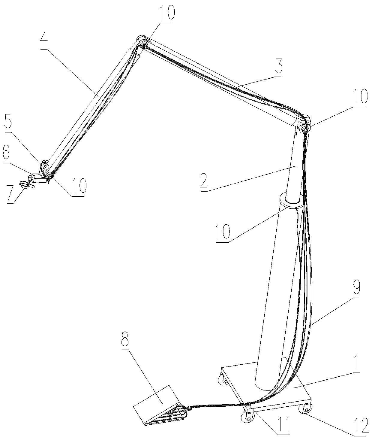
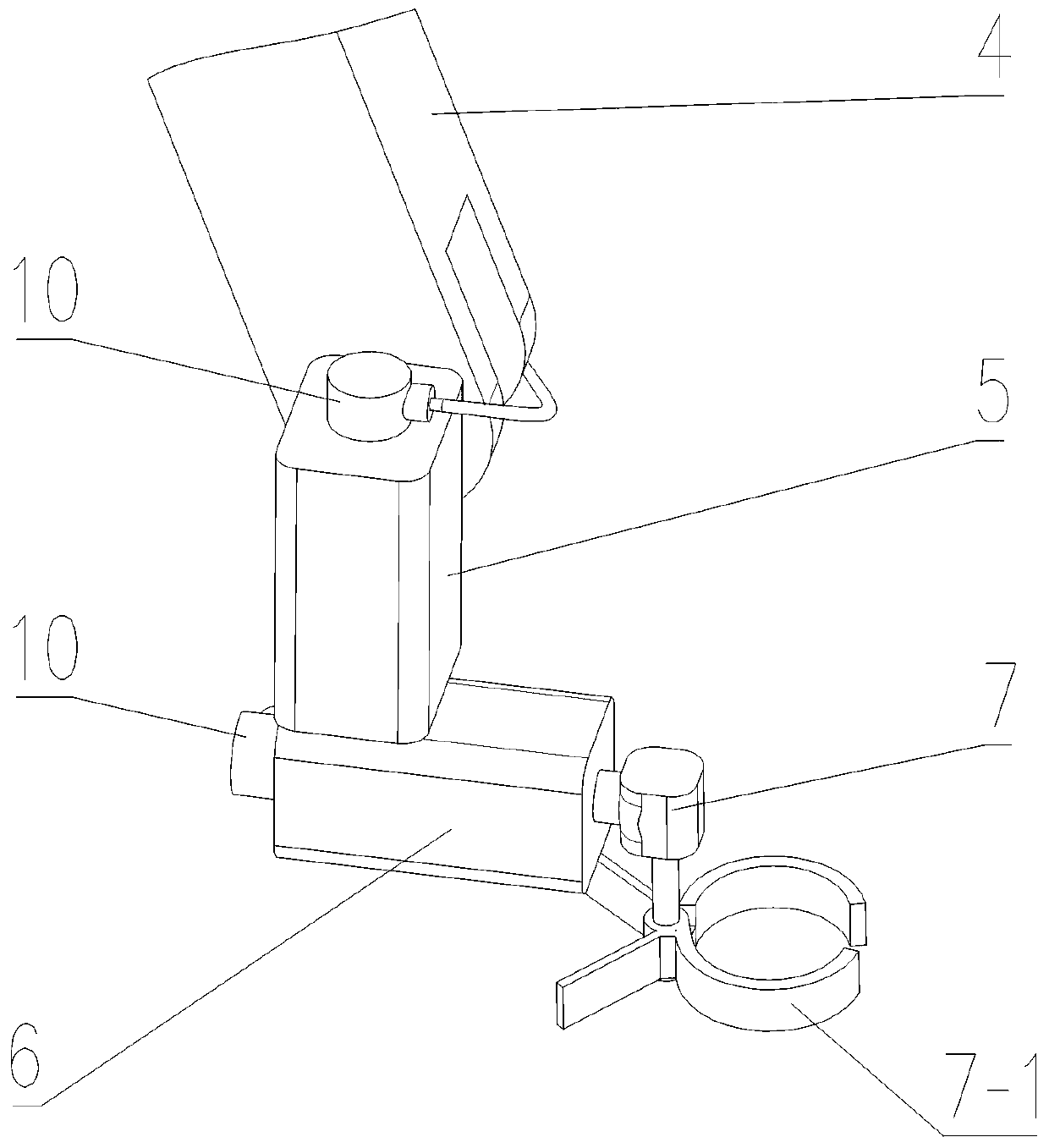
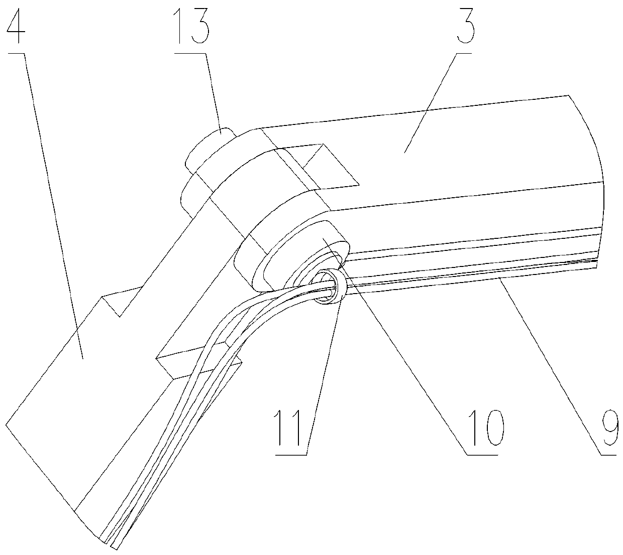
[0047] Example 1, when performing ultrasound-guided puncture on a patient, the doctor first selects an appropriate fixer (7-1), connects the fixer (7-1) to the rotating arm VI (7), and then inserts the ultrasound probe Fastened to the holder (7-1). Then hold the ultrasound probe to find a suitable puncture position on the patient. When a suitable position is found, the doctor can depress the pedal assembly (8), and the end of the sliding plate (8-3) slides toward the side of the brake shaft I (8-6), so that the pedal spring (8-4) is compressed, and at the same time 6 brake lines (9) are tightened, and the brake lines (9) move toward the brake shaft I (8-6) side along with the end of the sliding plate (8-3). After the brake cable (9) is tightened, each brake cable (10-6) moves with the brake cable (9), so that each brake pad (10-3) is tightened inward and tightly attached to the friction surface (14), to play the role of rotating arm I (2), rotating arm II (3), rotating arm I...
Embodiment 2
[0048] Embodiment 2, when the photographer is taking pictures, first select a suitable holder (7-1), connect the holder (7-1) with the rotating arm VI (7), and then fix the camera on the holder (7-1) superior. At this time, the camera is not constrained, and the photographer can hold the camera, and adjust the position and angle of the camera in six degrees of freedom in space. When the proper position is reached, the photographer steps on the pedal assembly (8), and the camera will be completely Tethered, the photographer can press the shutter and take a stable picture.
[0049] The above-mentioned X, Y, and Z directions are only for expressing and distinguishing the rotation direction of each revolving pair more clearly, rather than the expression method of the Cartesian coordinate system. For example, the X and Y directions are perpendicular to the Z direction, but the X direction There is a possibility of being parallel to the Y direction.
PUM
 Abstract
Description
Claims
Application Information
 - R&D Engineer
- R&D Manager
- IP Professional
- Industry Leading Data Capabilities
- Powerful AI technology
- Patent DNA Extraction
Browse by: Latest US Patents, China's latest patents, Technical Efficacy Thesaurus, Application Domain, Technology Topic, Popular Technical Reports.
© 2024 PatSnap. All rights reserved.Legal|Privacy policy|Modern Slavery Act Transparency Statement|Sitemap|About US| Contact US: help@patsnap.com


