
Anti-electric shock intelligent electric control cabinet and using method thereof

A technology for electric shock prevention and control cabinets, which is applied in the direction of measuring current/voltage, electrical components, circuit devices, etc., can solve the problems of simple structure of power distribution cabinets, lack of remote monitoring and control, and unfavorable remedial operations, etc., to prolong the service life , to facilitate real-time monitoring of the effect

Inactive Publication Date: 2020-06-23
中交三公局第一工程有限公司
View PDF10 Cites 1 Cited by
  • Summary
  • Abstract
  • Description
  • Claims
  • Application Information

AI Technical Summary

Problems solved by technology

[0004] The purpose of the present invention is to provide an anti-shock intelligent electric control cabinet and its use method, which has remote monitoring and control, and the data is synchronized to the operator, which is convenient for the operator to monitor in real time. The advantages of shock resistance and intelligent heat dissipation solve the problem of existing distribution The structure of the electric cabinet is simple, and it does not have the function of remote monitoring and control. After the electrical component circuit fails, the operator cannot be notified in time, and various data parameters cannot be effectively synchronized to the remote operator, which is not conducive to the operator's rapid adoption. Remedial operation, does not have the function of anti-seismic and intelligent heat dissipation, which reduces the problem of the applicability of the electric control cabinet

Method used


Image

  • Anti-electric shock intelligent electric control cabinet and using method thereof
  • Anti-electric shock intelligent electric control cabinet and using method thereof
  • Anti-electric shock intelligent electric control cabinet and using method thereof

Examples


Embodiment Construction

[0029] The following will clearly and completely describe the technical solutions in the embodiments of the present invention with reference to the accompanying drawings in the embodiments of the present invention. Obviously, the described embodiments are only some, not all, embodiments of the present invention. Based on the embodiments of the present invention, all other embodiments obtained by persons of ordinary skill in the art without making creative efforts belong to the protection scope of the present invention.

[0030]In the description of the invention, it should be noted that the terms "upper", "lower", "inner", "outer", "front end", "rear end", "both ends", "one end", "another end" etc. The indicated orientation or positional relationship is based on the orientation or positional relationship shown in the drawings, and is only for the convenience of describing the present invention and simplifying the description, rather than indicating or implying that the referred...


PUM


Abstract

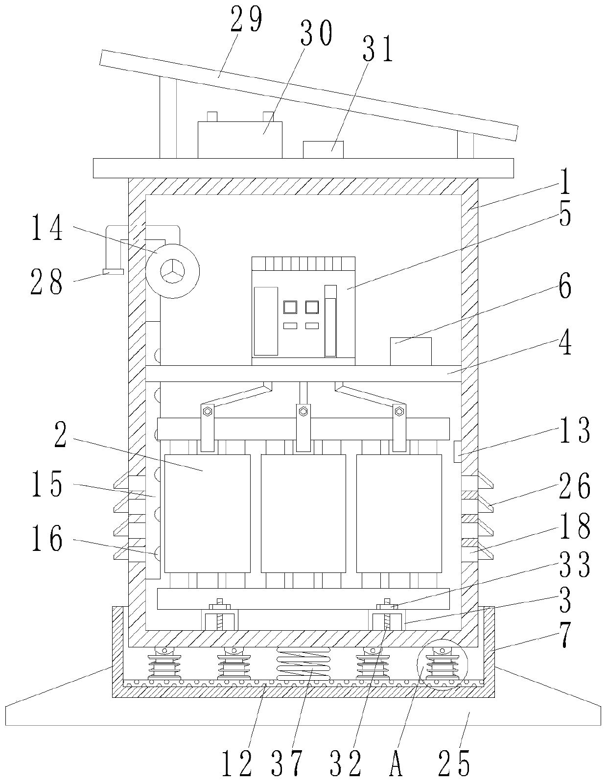
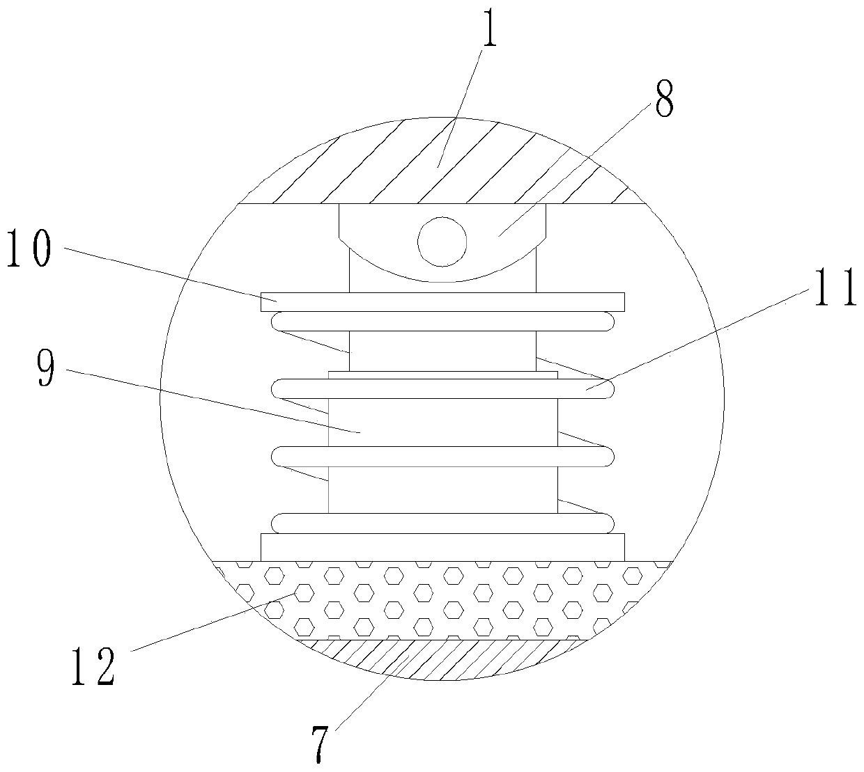
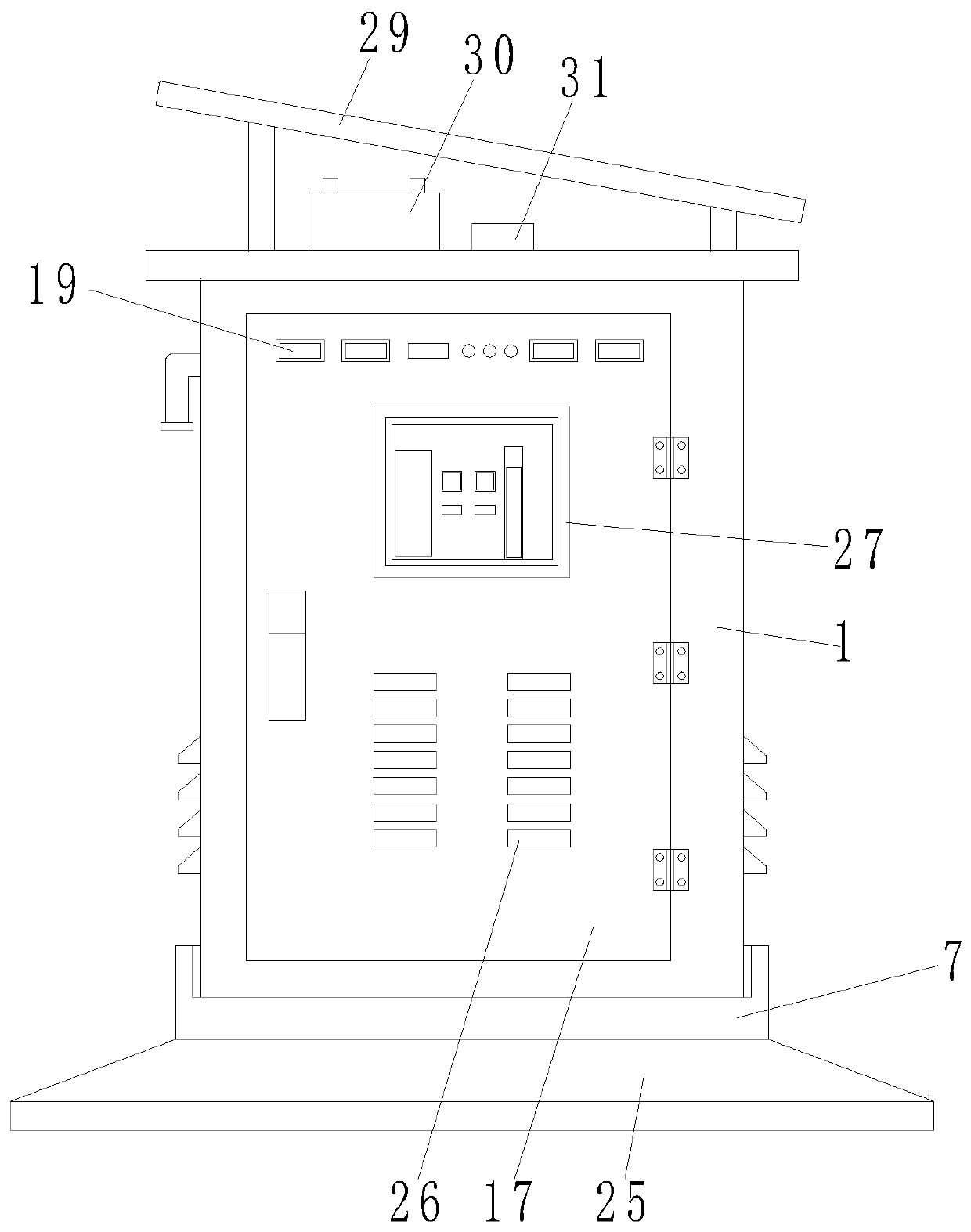
The invention discloses an anti-electric shock intelligent electric control cabinet and a use method thereof. The anti-electric shock intelligent electric control cabinet comprises a cabinet body, a dry-type transformer is arranged in an inner cavity of the cabinet body, U-shaped plates are fixedly connected to the two sides of the bottom of the dry-type transformer, the bottoms of the U-shaped plates make contact with the bottom of the inner cavity of the cabinet body, a support is transversely and fixedly connected to the inner cavity of the cabinet body, and the support is located above thedry-type transformer. The invention has the advantages of remote monitoring and control, and shock resistance and intelligent heat dissipation, and is advantageous in that data is synchronized to begiven to operators, and real time monitoring by the operators is facilitated; and the invention solves the problems that the existing power distribution cabinet has simple structure, does not have thefunctions of remote monitoring and control, cannot timely inform operators after the circuit of the electrical component fails, cannot effectively synchronize each data parameter to the remote operators, is not beneficial to the operators to quickly take remedial operation, does not have the functions of anti-vibration and intelligent heat dissipation, and reduces the applicability of the electrical control cabinet.

Description

technical field [0001] The invention relates to the technical field of electric control cabinets, in particular to an electric shock-proof intelligent electric control cabinet and a use method thereof. Background technique [0002] Electric control cabinet is to assemble switchgear, measuring instrument, protective device and auxiliary equipment in closed or semiclosed metal cabinet or on screen width according to electrical wiring requirements, and its layout should meet the requirements of normal operation of power system, and is easy to overhaul and does not endanger people. Safety control cabinets (boxes) for personal and surrounding equipment, including (distribution cabinets) (distribution boxes) (electrical control cabinets), etc. During normal operation, manual or automatic switches can be used to connect or break the circuit. During operation, it can cut off the circuit or alarm with the help of protective electrical appliances, and can display various parameters in...

Claims


Application Information

Patent Timeline
Patent Type & Authority Applications(China)
IPC IPC(8): H02J13/00H02B1/56H02B1/54G01R19/165G01K1/02G01K1/024
CPCH02B1/565H02B1/54G01R19/165G01K1/02Y04S10/40
Inventor 吴豪张世杰张可宇李鹏
Owner 中交三公局第一工程有限公司
Learn More