
Safety pneumatic integrated control valve and control method

An integrated control valve and safety technology, applied in the direction of fluid pressure actuators, servo motor components, mechanical equipment, etc., can solve the problems of safety and hidden dangers in the electronic control system

Pending Publication Date: 2020-06-23
ONGOAL MATERIAL AUTOMATION EQUIP
View PDF0 Cites 0 Cited by
  • Summary
  • Abstract
  • Description
  • Claims
  • Application Information

AI Technical Summary

Problems solved by technology

[0003] In order to overcome the deficiencies of the prior art, one of the purposes of the present invention is to provide a safe pneumatic integrated control valve, which can solve the problems of potential safety hazards in the use of electronic control systems in flammable and explosive occasions in the prior art.
[0004] The second object of the present invention is to provide a control method for a safe pneumatic integrated control valve, which can solve the problems of potential safety hazards in the use of electronic control systems in flammable and explosive occasions in the prior art

Method used


Image

  • Safety pneumatic integrated control valve and control method
  • Safety pneumatic integrated control valve and control method

Examples


Embodiment 1

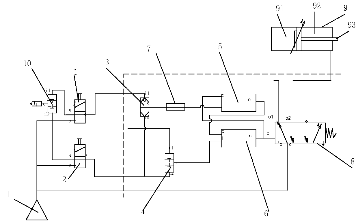
[0041] Such as figure 1 As shown, the present invention provides a preferred embodiment, a safety pneumatic integrated control valve, including two manually operated valves, a first double pressure valve 4, a shuttle valve 3, a forbidden door valve to control the air circuit, a single air control two Position five-way valve 8 and cylinder 9.

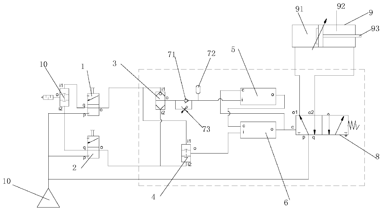
[0042] In addition, in order to easily distinguish the various ports of the valve, such as figure 1 As shown, the present invention makes the following marks: o represents the output port, o1 represents the first output port, o2 represents the second output port, i represents the input port, i1 represents the first input port, i2 represents the second input port, p represents the gas Source port, q means exhaust port, and d means air control port.

[0043] Wherein, the manual operation valve is provided with an air source port, an exhaust port and an output port. When the manual operation valve is connected, the air source port is con...

Embodiment 2

[0111] Based on Embodiment 1, the present invention also provides a control method for a safety pneumatic integrated control valve, including the following steps:

[0112] Step (1): When the first manual operation valve and the second manual operation valve are synchronously connected, the pressure first reaches the input port of the second prohibition valve control air circuit of the prohibition valve through the second double pressure valve, so that the second The output port of the ban door valve outputs pressure to the air control end of the single air control two-position five-way valve, and then controls the valve core of the single air control two-position five-way valve to move under the action of pressure against the spring force, so that the single air The air source port of the two-position five-way valve is connected to the first output port of the single-air control two-position five-way valve, and the exhaust port of the single-air control two-position five-way va...


PUM


Abstract

The present invention discloses a safety pneumatic integrated control valve. By arranging two manual operation valves, a user simultaneously presses the two manual operation valve, and pressure is input to the air control end of a single-air-control two-position five-way valve by a door valve control air path, thereby realizing control of a cylinder. The manual operation valves are pressed simultaneously with both hands to realize action control of the cylinder, so that a worker can be prevented from being injured as the worker presses the operation valve with one hand and operates a workpiecewith the other hand or is in a dangerous position. The invention also discloses a control method of the safety pneumatic integrated control valve.

Description

technical field [0001] The invention relates to a manual control valve, in particular to a safety pneumatic integrated control valve and a control method. Background technique [0002] Generally, for the buttons of the electric control, electric or pneumatic control system, in the prior art, the two electric buttons are pressed at the same time by both hands and the pneumatic actuator is controlled by the solenoid valve to realize the control action. In flammable and explosive places, it is easy to cause danger when the button adopts an electronic control system. Contents of the invention [0003] In order to overcome the deficiencies of the prior art, one of the purposes of the present invention is to provide a safety pneumatic integrated control valve, which can solve the problems of potential safety hazards in the use of electronic control systems in flammable and explosive occasions in the prior art. [0004] The second object of the present invention is to provide a ...

Claims


Application Information

Patent Timeline
IPC IPC(8): F15B13/04F15B13/02
CPCF15B13/0401F15B13/02F15B2013/002
Inventor 余子毅骆清文
Owner ONGOAL MATERIAL AUTOMATION EQUIP
Learn More