
Movable mounting base for ship electrical equipment

A technology for electrical equipment and installation bases, applied in the field of movable installation bases, can solve the problems of limited space, large modification and modification workload, etc., and achieve the effect of convenient on-site construction, convenient equipment use, and improved maintenance space

Inactive Publication Date: 2020-06-23
CSSC HUANGPU WENCHONG SHIPBUILDING COMPANY
View PDF11 Cites 2 Cited by
  • Summary
  • Abstract
  • Description
  • Claims
  • Application Information

AI Technical Summary

Problems solved by technology

[0002] At present, the traditional ship electrical equipment installation type is fixed by bolts or directly welded on the equipment base. This installation type is no problem for cabins with relatively large cabin space and enough space for equipment maintenance. However, the actual ship cabin space is limited, and often There will be situations where the installation space of electrical equipment is not large enough to affect equipment maintenance, and there will be multiple electrical equipment in the same cabin. If there are several equipment with relatively high maintenance space requirements, it is easy to cause the electrical equipment in the entire cabin to be unreasonably arranged as required. , resulting in cabin structure modification or electrical equipment adjustment and installation cabin, the modification workload is very large

Method used


Image

  • Movable mounting base for ship electrical equipment
  • Movable mounting base for ship electrical equipment
  • Movable mounting base for ship electrical equipment

Examples


no. 1 approach

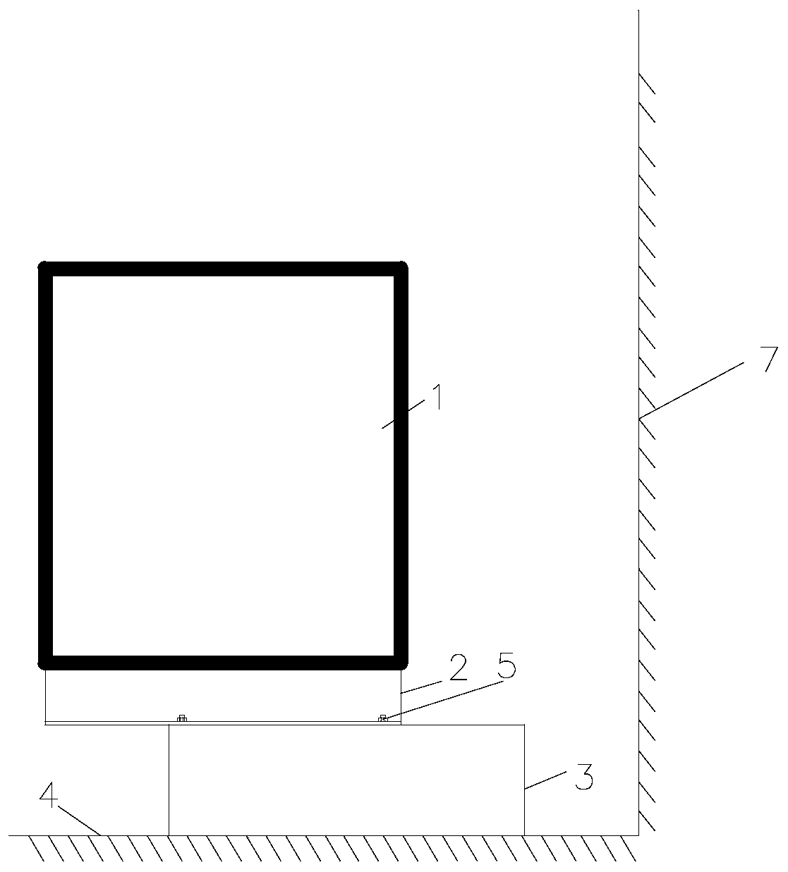
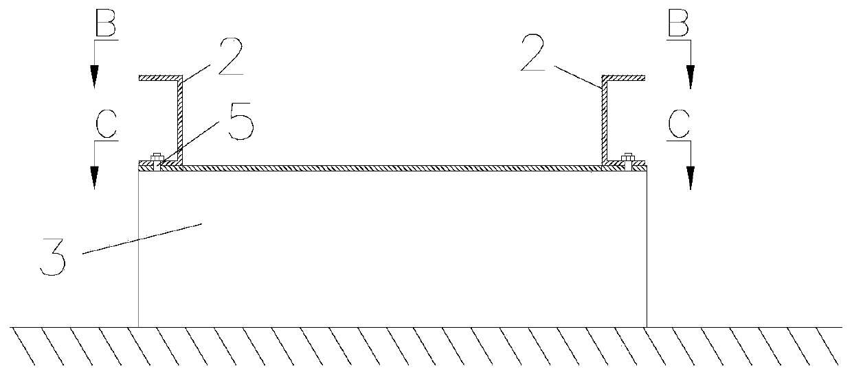
[0032] like figure 1 and figure 2 As shown, this embodiment provides a movable installation base for electrical equipment 1 of a ship. The electrical equipment 1 is placed in the cabin of the ship. The installation base includes a fixed module 3, a mobile module 2 and a connection assembly 5. The fixed module 3 is fixedly installed on the deck 4 of the cabin, the upper end of the fixed module 3 is movably connected with the lower end of the mobile module 2 through the connection assembly 5 , and the electrical equipment 1 is fixedly connected with the upper end of the mobile module 2 .

[0033] The fixed module 3 is fixedly connected with the deck 4, which can be arranged at a position close to the cabin bulkhead 7, and then the electrical equipment 1 is fixedly connected with the mobile module 2, because the mobile module 2 is slidably connected with the fixed module 3, in the working state, such as figure 1 As shown, the electrical equipment 1 is closer to the bulkhead 7, ...

no. 2 approach

[0042] like Image 6 and Figure 7As shown, the mobile module 2 of the present embodiment has the same structure as the mobile module 2 of the previous embodiment, but the fixed module 3 of the present embodiment includes a moving block 10, a fixed block 8 and a supporting block 9, and the lower side of the fixed block 8 is connected to the The deck 4 of the cabin is fixedly connected, the inclined surface of the fixed block 8 is slidably connected with the inclined surface of the moving block 10, and the upper side of the moving block 10 is the upper side of the fixed module 3;

[0043] Both the moving block 10 and the fixed block 8 are right-angled triangular prisms, the inclined surfaces of the two right-angled triangular prisms are slidable, and the right-angled faces and sides of the two right-angled triangular prisms form a rectangular block, and the apex side of the fixed block 8 faces the bulkhead 7 of the cabin , the inclined surface of the fixed block 8 is provided ...

Embodiment approach

[0050] like Image 6 and Figure 7 As shown, this embodiment is actually a supplementary embodiment of the second embodiment. On the basis of the second embodiment, a support assembly 11 is added on the fixed block 8. The support assembly 11 includes a first support plate 14, a second Two support plates 13 and a telescopic support bar 12, the first support plate 14 and the second support plate 13 are arranged in parallel, and the two ends of the telescopic support bar 12 are respectively fixedly connected with the first support plate 14 and the second support plate 13, The first support plate 14 is supported on the bottom surface of the mobile block 10, the second support plate 13 is supported on the bulkhead 7, and the telescopic support rod 12 is a manual air pressure telescopic rod, a manual hydraulic telescopic rod or an electric telescopic rod, which is telescopic. The number of support rods 12 is at least two, and they are all arranged in parallel.

[0051] The reason ...


PUM


Abstract

The invention provides a movable mounting base for ship electrical equipment. The electrical equipment is placed in the cabin of the ship. The mounting base comprises a fixed module, a movable moduleand a connecting assembly; the fixed module is fixedly mounted on the deck of the cabin; the upper end of the fixed module is movably connected with the lower end of the movable module through the connecting assembly; and the electrical equipment is fixedly connected with the upper end of the movable module. According to the movable mounting base of the invention, the electrical equipment is fixedon the movable module; the movable module is movably connected with the fixed module, so that the electrical equipment can be moved to be far away from a cabin wall when needing to be overhauled, andtherefore, overhauling space of the electrical equipment is improved; and during normal work, the electrical equipment is close to the cabin wall, so that the occupation of a public area is reduced;and therefore, the whole cabin is more reasonable in arrangement, the use and maintenance of the equipment are facilitated, and on-site construction is facilitated.

Description

technical field [0001] The present disclosure relates to the field of electrical installation, in particular to a movable installation base for marine electrical equipment. Background technique [0002] At present, the traditional ship electrical equipment installation type is fixed by bolts or directly welded on the equipment base. This installation type is no problem for cabins with relatively large cabin space and enough space for equipment maintenance. However, the actual ship cabin space is limited, and often There will be situations where the installation space of electrical equipment is not large enough to affect equipment maintenance, and there will be multiple electrical equipment in the same cabin. If there are several equipment with relatively high maintenance space requirements, it is easy to cause the electrical equipment in the entire cabin to be unreasonably arranged as required. , resulting in the modification of the cabin structure or the adjustment and inst...

Claims


Application Information

Patent Timeline
IPC IPC(8): B63B17/00
CPCB63B17/00B63B2017/0054
Inventor 余勇林唐彪李春明张远飞黄春华陈志宇
Owner CSSC HUANGPU WENCHONG SHIPBUILDING COMPANY
Learn More