
Middle driving mechanism and power-assisted bicycle

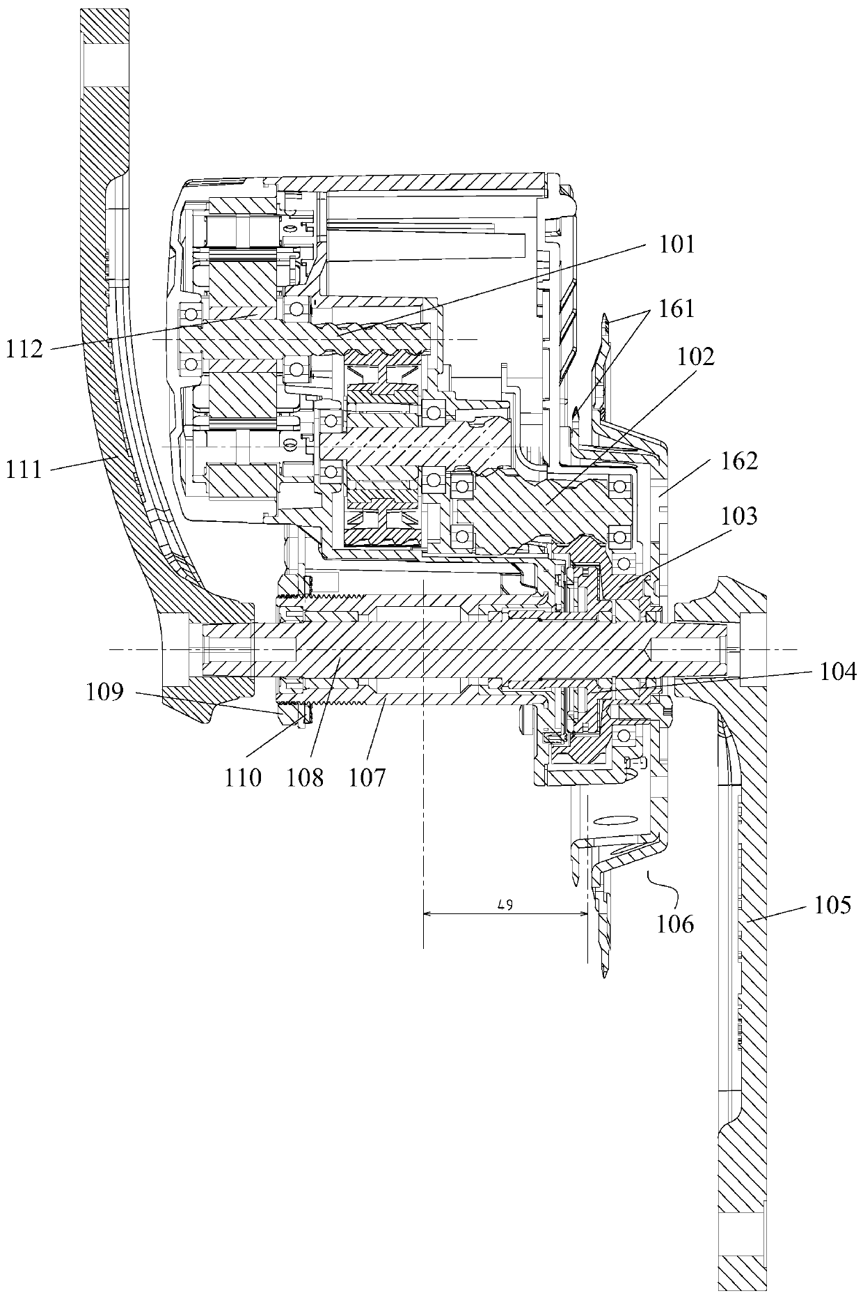
A technology for assisting bicycles and driving mechanisms, applied in the directions of rider driving, vehicle components, vehicle gearboxes, etc., can solve the problems of large distance and occupy the axial space of the central axis, and achieve the effect of shortening the distance and preventing the distance from being too far.

Pending Publication Date: 2020-06-23
SUZHOU WANJIA ELECTRIC
View PDF0 Cites 2 Cited by
  • Summary
  • Abstract
  • Description
  • Claims
  • Application Information

AI Technical Summary

Problems solved by technology

The central driving mechanism includes the motor and the central shaft installed on the frame. The central shaft is inserted into the bushing, and the bushing is accommodated in the shaft hole of the frame and fixed by fastening metal parts; the central shaft is fitted with a coaxial device. The auxiliary gear and the crankset, the auxiliary gear cooperates with the reduction mechanism, and the crankset is used to assemble the chain; among them, the auxiliary gear occupies the axial space of the center shaft, causing the crankset to be far away from the frame, resulting in the plane where the chain matched with the crankset is different from the The frame distance is too large

Method used


Image

  • Middle driving mechanism and power-assisted bicycle

Examples


Embodiment Construction

[0032] The embodiment of the present invention discloses a middle drive mechanism for power-assisted bicycles. The tooth plate includes a mounting part and a tooth part. The mounting part is used to accommodate the auxiliary gear. The tooth part straddles the auxiliary gear and is close to the frame. The distance between the frames is shortened, effectively reducing the distance between the chain and the frame. The embodiment of the present invention also discloses a power-assisted bicycle, which uses the above-mentioned middle drive mechanism to avoid too far distance between the chain and the frame.

[0033] The following will clearly and completely describe the technical solutions in the embodiments of the present invention with reference to the accompanying drawings in the embodiments of the present invention. Obviously, the described embodiments are only some, not all, embodiments of the present invention. Based on the embodiments of the present invention, all other embod...


PUM


Abstract

The invention discloses a middle driving mechanism. The mechanism is used for a power-assisted bicycle and comprises a middle shaft, a chain wheel and a motor; the middle shaft is inserted into a shaft hole of a middle frame of the power-assisted bicycle; an auxiliary gear sleeves the middle shaft in a fixed manner; the chain wheel comprises an installation part located in the center and a tooth part fixed to the periphery of the installation part; the installation part protrudes in an axial direction and forms a containing cavity; the tooth part is located at the end, close to the frame, of the installation part in an axial direction; the installation part sleeves the middle shaft and is fixedly connected with the auxiliary gear; the auxiliary gear is positioned in the containing cavity;and the motor is assembled on the frame and drives the auxiliary gear to rotate through a speed reduction assembly. In the middle driving mechanism, the tooth part in the chain wheel achieves the effect of crossing the auxiliary gear to be close to the frame, so that the distance between the tooth part and the frame is effectively shortened, and therefore, the distance between a chain and the frame will not be too long. The invention further discloses a power-assisted bicycle. The power-assisted bicycle is provided with the middle driving mechanism, so that the distance between the chain and the frame will not be too long.

Description

technical field [0001] The present invention relates to the technical field of bicycles, more specifically, to a middle drive mechanism, and also to a power-assisted bicycle. Background technique [0002] The power-assisted bicycle is a kind of battery as the auxiliary power source, equipped with a motor, and equipped with a power auxiliary system, which can realize the integration of human riding and motor-assisted power. [0003] In the field of power-assisted bicycles, the motor is installed in the middle of the vehicle frame and forms a central drive mechanism. The central driving mechanism includes the motor and the central shaft installed on the frame. The central shaft is inserted into the bushing, and the bushing is accommodated in the shaft hole of the frame and fixed by fastening metal parts; the central shaft is fitted with a coaxial device. Auxiliary gear and crankset, the auxiliary gear cooperates with the reduction mechanism, and the crankset is used to assemb...

Claims


Application Information

Patent Timeline
Patent Type & Authority Applications(China)
IPC IPC(8): B62M6/45B62M6/50B62M6/55B62M11/06
CPCB62M6/45B62M6/50B62M6/55B62M11/06
Inventor 黄福明马诚黄俊宁蔡华林余军辉
Owner SUZHOU WANJIA ELECTRIC
Learn More