a rotor core

A rotor core and rotor punching technology, which is applied in the field of rotor cores, can solve the problems of rotor punching deviation and large error, and achieve the effect of improving work efficiency and convenient operation

Active Publication Date: 2022-03-29
安徽博克士电子有限公司
View PDF12 Cites 0 Cited by
  • Summary
  • Abstract
  • Description
  • Claims
  • Application Information

AI Technical Summary

Problems solved by technology

[0003] During the processing of the rotor core inside the large motor, the rotor core is welded by stacking multiple rotor punches. The welding process needs to align the cooling holes on the multiple rotor punches to prevent welding deviation. Currently Alignment and stacking are done by human visual inspection, and the error is relatively large, and the rotor punches are also easily deviated by external forces after stacking

Method used


Image

  • a rotor core
  • a rotor core
  • a rotor core

Examples


Embodiment Construction

[0019] The present invention will be further described below in conjunction with the accompanying drawings and embodiments.

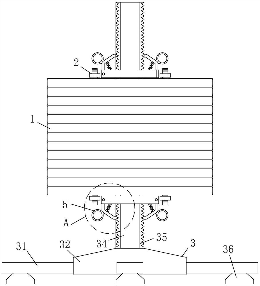
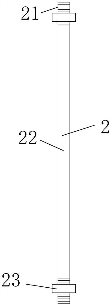
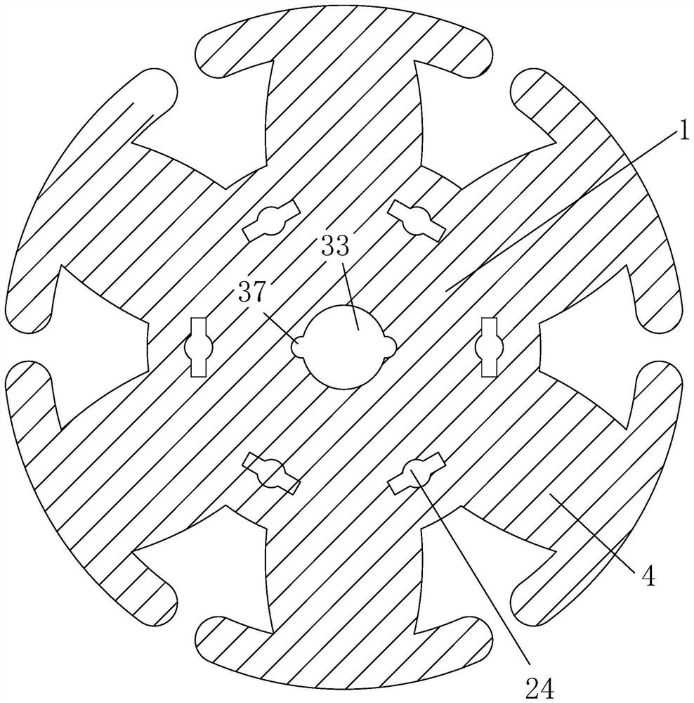
[0020] Please refer to figure 1 , figure 2 , image 3 , Figure 4 and Figure 5 , a rotor core, including a rotor punch 1, a positioning guide structure 2, a support structure 3 and a clamping structure 4, the number of the rotor punch 1 is several pieces, and several pieces of rotor punches are stacked, and two adjacent Two rotor punches 1 are welded and connected, and the positioning and guiding structure 2 is connected to the rotor punching 1. The positioning and guiding structure 2 includes external threads 21, positioning columns 22 and limit bars 23, and the surface of the rotor punching 1 is provided with several A surrounding heat dissipation positioning cavity 24, one end of the positioning column 22 runs through a plurality of stacked rotor punches 1, the heat dissipation positioning cavity 24, the outer walls of the two ends of the posit...


PUM


Abstract

The invention relates to the field of iron cores, in particular to a rotor iron core, which includes a rotor punching piece, a positioning guide structure, a supporting structure and a clamping structure. The positioning and guiding structure is connected to the rotor punching piece, and the positioning and guiding structure includes External thread, positioning column and limit cross bar. The surface of the rotor punching sheet is provided with several heat dissipation positioning cavities arranged around it. One end of the positioning column passes through several heat dissipation positioning cavities on the stacked rotor punching pieces. The outer side walls at both ends of the positioning column are respectively An external thread is provided, and the two ends of the positioning column are threadedly connected to the limit cross bar; the supporting structure is connected to the rotor punching piece, and the number of the clamping structures is two, and the two clamping structures are connected to the supporting structure. The rotor iron core provided by the invention has the advantages of a guiding and positioning structure, which is not easily affected by external influences after being sleeved, and can be quickly stacked in a corresponding manner.

Description

technical field [0001] The invention relates to the field of iron cores, in particular to a rotor iron core. Background technique [0002] The motor rotor is also the rotating part in the motor. The motor consists of two parts, the rotor and the stator, which are used to realize the conversion of electrical energy and mechanical energy and mechanical energy and electrical energy. The motor rotor is divided into a motor rotor and a generator rotor. [0003] During the processing of the rotor core inside the large motor, the rotor core is welded by stacking multiple rotor punches. The welding process needs to align the cooling holes on the multiple rotor punches to prevent welding deviation. Currently Alignment and stacking are performed by human visual inspection, and the error is relatively large, and the rotor punches are also easily deviated by external forces after stacking. Therefore, it is necessary to provide a new rotor core to solve the above technical problems. ...

Claims


Application Information

Patent Timeline
Patent Type & Authority Patents(China)
IPC IPC(8): H02K15/02
CPCH02K15/02
Inventor 杨帅军王金玉
Owner 安徽博克士电子有限公司
Why Eureka
Try Eureka