Laser projection device

A technology of laser projection and equipment, which is applied in optics, instruments, projection devices, etc., can solve problems such as high startup efficiency and low startup noise.

Active Publication Date: 2020-06-19
QINGDAO HISENSE LASER DISPLAY CO LTD
View PDF17 Cites 2 Cited by
  • Summary
  • Abstract
  • Description
  • Claims
  • Application Information

AI Technical Summary

Problems solved by technology

[0005] This application provides a laser projection device, which can solve the problem that the laser projection device in the related art cannot take into account high start-up efficiency and low start-up noise

Method used


Image

  • Laser projection device
  • Laser projection device
  • Laser projection device

Examples


Embodiment Construction

[0029] In order to make the purpose, technical solution and advantages of the present application clearer, the implementation manners of the present application will be further described in detail below in conjunction with the accompanying drawings.

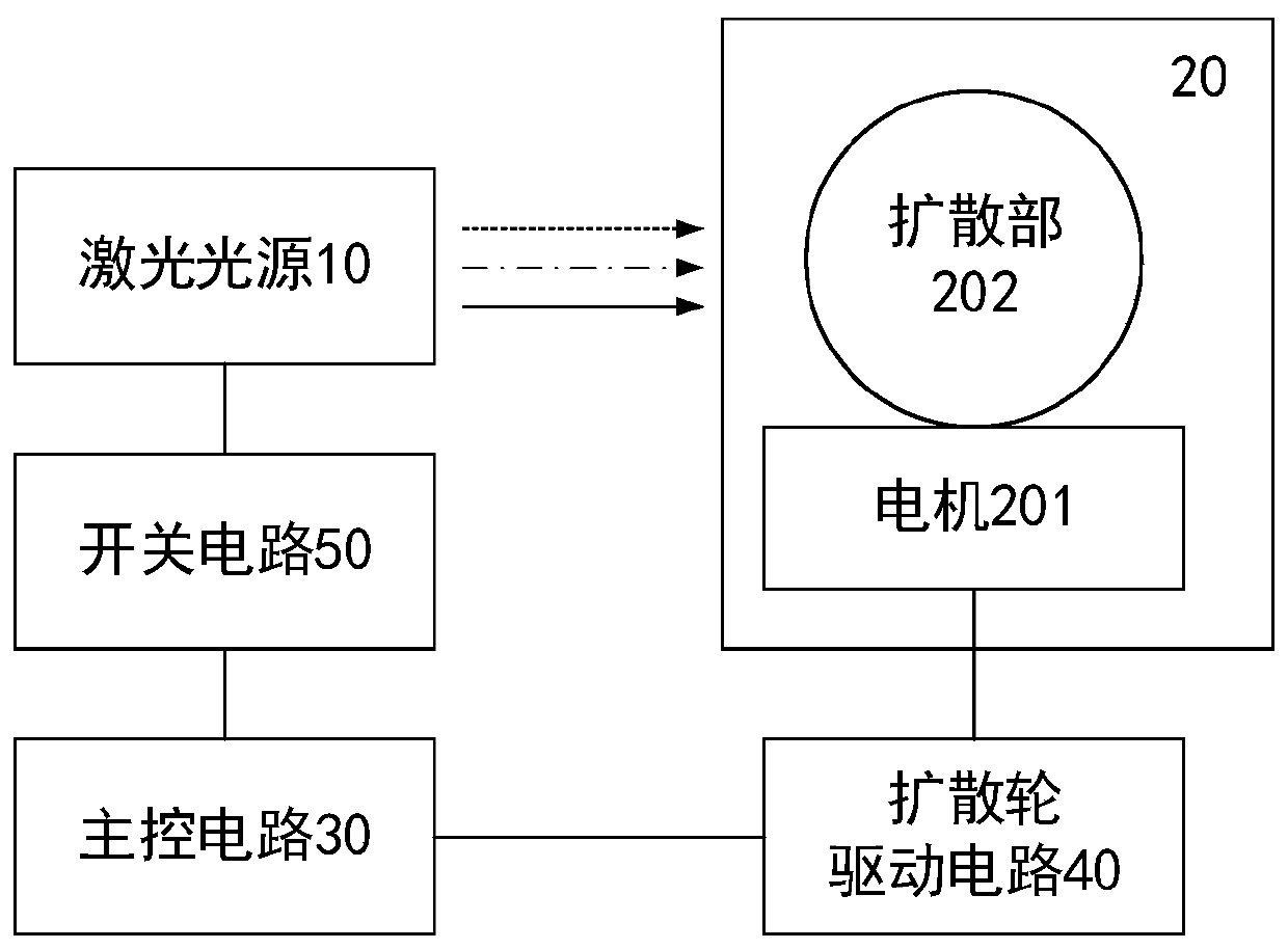
[0030] The embodiment of the present application provides a laser projection device, such as figure 1 As shown, the device may include: a laser light source 10 , a diffusion wheel 20 , a main control circuit 30 , a diffusion wheel drive circuit 40 and a switch circuit 50 . Wherein, the diffusion wheel 20 may include a motor 201 and a diffusion part 202 connected with the motor 201 .

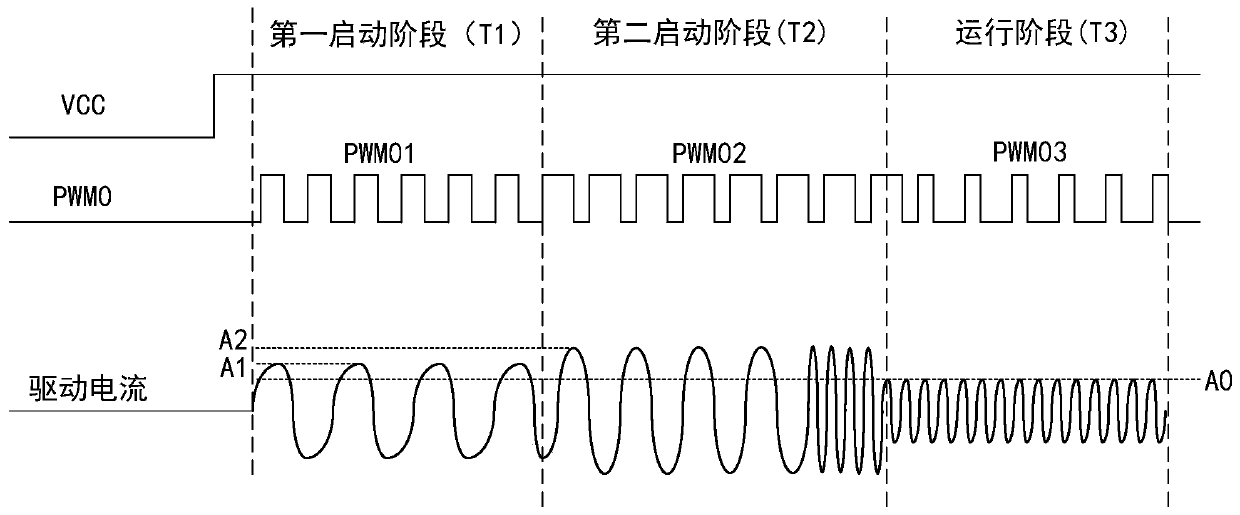
[0031] The main control circuit 30 is respectively connected with the diffusion wheel drive circuit 40 and the switch circuit 50, and the main control circuit 30 is used to sequentially output the first start pulse width modulation signal and the second pulse width modulation signal to the diffusion wheel drive circuit 40 in response to the boot com...


PUM


Abstract

The invention discloses laser projection equipment, and belongs to the field of laser projection display. A main control circuit in the equipment can provide a first starting pulse width modulation signal and a second starting pulse width modulation signal to a diffusion wheel driving circuit in sequence in response to a starting instruction, and the duty ratio of the second starting pulse width modulation signal is larger than that of the first starting pulse width modulation signal; and the diffusion wheel driving circuit is used for driving a motor in the diffusion wheel to rotate under thedriving of the pulse width modulation signal provided by the main control circuit. In the starting-up process, the starting-up speed is high, the diffusion wheel drive circuit can slowly start the motor based on a first start pulse width modulation signal with a small duty ratio. Therefore, the duration that the main control circuit provides the second starting pulse width modulation signal withthe large duty ratio for the diffusion wheel driving circuit can be shortened, the starting efficiency can be guaranteed, meanwhile, noise generated in the motor starting process can be effectively reduced, and high starting efficiency and low starting noise can be both considered.

Description

technical field [0001] The present application relates to the field of laser projection display, in particular to a laser projection device. Background technique [0002] Laser projection equipment generally includes a light source system, an illumination system and a lens system. The light source system is used to provide laser beams, the lighting system is used to modulate the laser beams into image beams, and the lens system is used to project the image beams onto the projection screen. Wherein, the light source system includes a laser light source and a diffusion wheel, and the diffusion wheel can diffuse the laser light emitted by the laser light source. [0003] In the related art, the light source system further includes a main control circuit and a driving circuit for driving the diffusion wheel. The main control circuit can provide a driving signal to the driving circuit according to the magnitude of the starting current required to start the diffusion wheel. The...

Claims


Application Information

Patent Timeline
IPC IPC(8): G09G3/00G03B21/20G03B21/00G03B21/16
CPCG03B21/008G03B21/16G03B21/208G09G3/001G09G2330/026G09G2330/027
Inventor 陈许肖纪臣
Owner QINGDAO HISENSE LASER DISPLAY CO LTD
Why Eureka
Try Eureka