
Intelligent card chip mounting visual detection system and detection method

A smart card chip and visual inspection technology, which is applied to measuring devices, instruments, scientific instruments, etc., can solve problems such as missed inspections and false inspections, and achieve the effects of reducing production costs, improving quality, and eliminating hidden dangers of product defects

Pending Publication Date: 2020-06-19
新恒汇电子股份有限公司
View PDF10 Cites 11 Cited by
  • Summary
  • Abstract
  • Description
  • Claims
  • Application Information

AI Technical Summary

Problems solved by technology

[0007] The technical problem to be solved by the present invention is: to overcome the deficiencies of the prior art, to provide a defect detection unit, and the carrier tape with the chip pasted is first detected by the defect detection unit before entering the curing furnace, which avoids the traditional manual inspection method. A smart card chip placement visual inspection system and inspection method that are prone to false detection and missed detection, and can detect defects that cannot be recognized by the naked eye, and can provide feedback on defects, eliminating hidden dangers of product defects

Method used


Image

  • Intelligent card chip mounting visual detection system and detection method
  • Intelligent card chip mounting visual detection system and detection method
  • Intelligent card chip mounting visual detection system and detection method

Examples


Embodiment Construction

[0056] Figure 1~13 It is the best embodiment of the present invention, below in conjunction with attached Figure 1~13 The present invention will be further described.

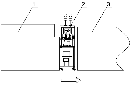
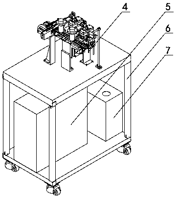
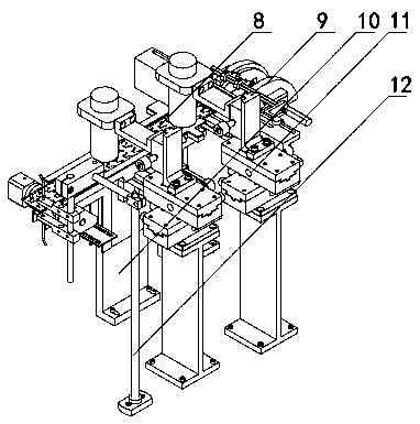
[0057] Such as figure 1 As shown, the smart card chip mounting visual inspection system (hereinafter referred to as the visual inspection system) includes a visual inspection mechanism 2 placed between the placement machine 1 and the curing furnace 3 of the traditional smart card production line. The carrier tape 8 of the chip is inspected and analyzed for defects, and the operating parameters of the chip mounter 1 are adjusted according to the defect feedback, so as to prevent a large number of defective products from entering the curing furnace 3 and effectively avoid economic losses. The direction of the arrow in the figure is The running direction of the carrier tape 8, in this application, is defined as the running direction of the carrier tape 8 from left to right, so other relative positions (directi...


PUM


Abstract

The invention discloses an intelligent card chip mounting visual detection system and detection method, which belong to the technical field of intelligent card production. The system is characterizedin that the system comprises a defect detection unit (4) and an industrial personal computer (5), and the defect detection unit (4) comprises a positioning mechanism (10), a counting mechanism (12), aphotographing mechanism (11) and a bad hole detection mechanism (9), wherein the counting mechanism (12), the photographing mechanism (11) and the bad hole detection mechanism (9) are behind the positioning mechanism. The method further comprises the steps of 1001 photographing a carrier tape by the photographing mechanism; 1002 positioning the area of the chip on the carrier tape; 1003 determining the relative position of the carrier tape (8) and the chip; 1004 carrying out glue dripping detection; 1005 identifying a glue overflowing area; 1006 calculating the percentage of the glue overflowing area; and step 1007 judging whether the carrier tape and the chip have defects or not. According to the intelligent card chip mounting visual detection system and detection method, the defect detection unit is arranged, so that the defects of false detection and missing detection easily occurring in a traditional manual detection mode are avoided, the defects can be fed back, and the hidden danger of product defects is eliminated.

Description

technical field [0001] A smart card chip mounting visual detection system and detection method belong to the technical field of smart card production. Background technique [0002] With the development of integrated circuits and the improvement of people's living standards, the application of smart cards has become more and more extensive. It has been widely used in telecommunications, banking, social security, logistics and other fields. The general process of the smart card is as follows: first, glue the carrier tape in the placement machine and paste the chip on the carrier tape, and then cure the glue in the curing furnace to fix the chip on the surface of the carrier tape. After curing, the chip is fixed on the carrier tape. The surface of the tape, and then solder the terminals on the chip to the corresponding terminals on the carrier tape, and then solidify and package the chip and its surrounding welding wires. [0003] When soldering the terminal of the chip and th...

Claims


Application Information

Patent Timeline
IPC IPC(8): G01N21/956G01N21/13
CPCG01N21/956G01N21/13
Inventor 刘帅程世翀
Owner 新恒汇电子股份有限公司
Learn More