Measuring device for determining fluid variable

A measurement device, fluid technology, applied in the direction of measurement device, fluid velocity measurement, vibration measurement in solids, etc., can solve the problems of complex photolithography, inability to achieve modal purity, inability to obtain high efficiency, etc., and achieve the effect of avoiding tension

Inactive Publication Date: 2020-06-19
DIEHL METERING
View PDF0 Cites 0 Cited by
  • Summary
  • Abstract
  • Description
  • Claims
  • Application Information

AI Technical Summary

Problems solved by technology

Since the shear mode of the piezoelectric element must be excited, the excitation usually cannot be achieved with high efficiency
Furthermore, relatively complex, highly precise lithography is required in order to apply the desired electrode structure with sufficient accuracy, however, a sufficient modal purity of the excitation cannot usually be achieved.

Method used


Image

  • Measuring device for determining fluid variable
  • Measuring device for determining fluid variable
  • Measuring device for determining fluid variable

Examples


Embodiment Construction

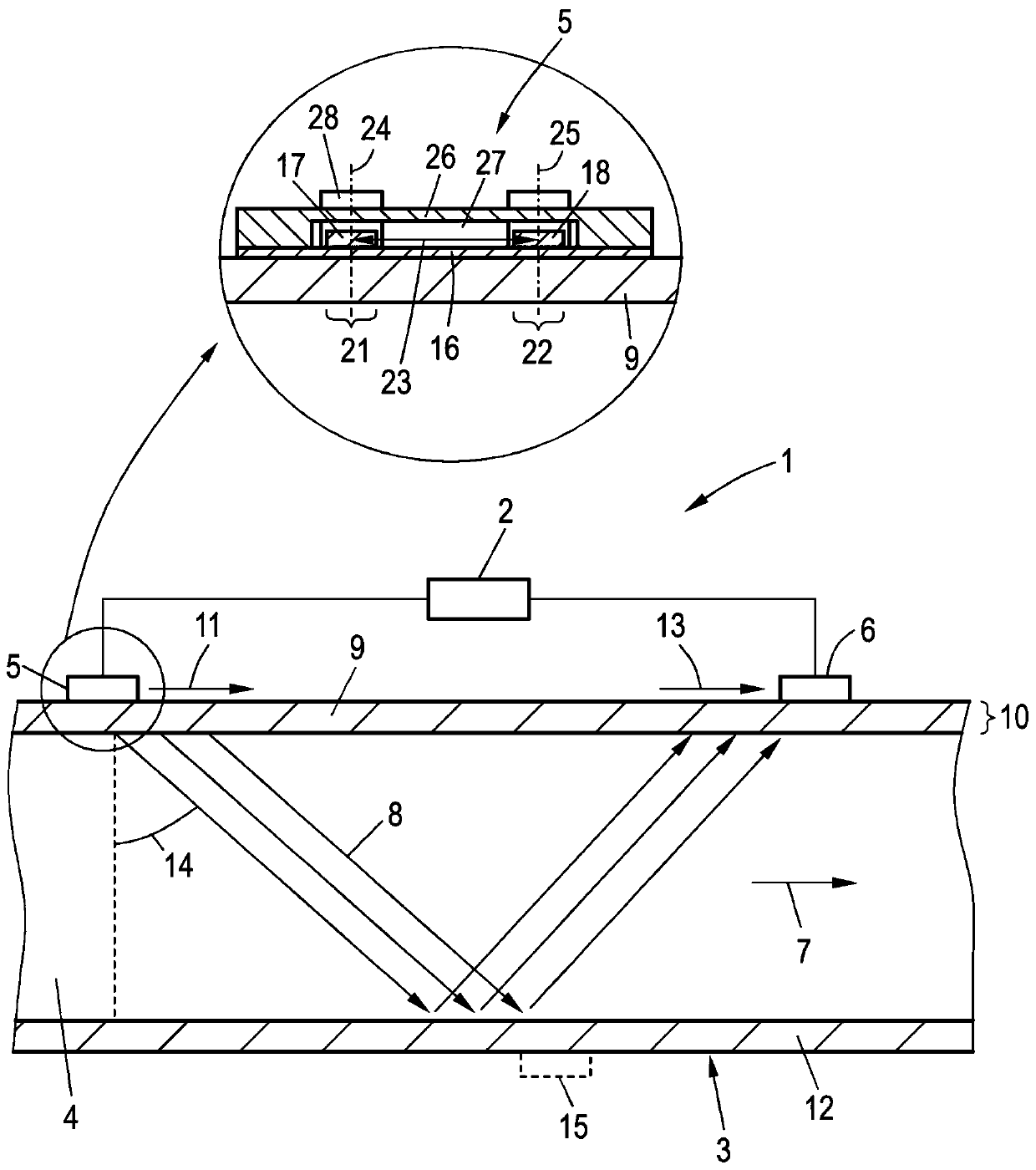
[0032] figure 1 A measuring device 1 for determining a fluid variable related to a fluid and / or fluid flow is shown. Here, the fluid is guided through the interior 4 of the measuring tube 3 in the direction indicated by the arrow 7 . In order to determine a fluid variable, in particular a volumetric flow rate, the control device 2 can determine from the first vibration transducer 5 to the second vibration transducer 6 and from the second vibration transducer 6 to the first vibration transducer 5 The transit time difference between the transit times of . Here, use is made of the fact that this transit time depends on the velocity component of the fluid parallel to the direction of propagation of the ultrasound beam 8 through the fluid. From this transit time the fluid velocity averaged over the path of the respective ultrasound beam 8 in the direction of the respective ultrasound beam 8 and thus approximately the average flow velocity in the volume through which the ultrasoun...


PUM


Abstract

A measuring device for determining a fluid variable includes a control device, a measuring tube and a first vibration transducer arranged at the measuring tube. The first vibration transducer containsa vibration element. The vibration element has a vibration body, a first electrode on the measuring tube side and a second electrode averted from the measuring tube. The first electrode extends overa first end face of the vibration body. The second electrode extends to a second end face that lies opposite the first end face. A respective conductive contact element contacts the first electrode ata first end face and the second electrode at a second end face electrically and mechanically such that the vibration element is supported by the contact elements. A voltage between the first and second electrodes can be varied through the vibration element to excite a guided wave in a side wall of the measuring tube.

Description

technical field [0001] The invention relates to a measuring device for determining a fluid variable related to a fluid and / or a fluid flow of a fluid, which has a control device, a measuring tube for receiving and / or guiding the fluid, and a The first vibration transducer at , wherein the first vibration transducer includes at least one vibration element. Background technique [0002] Ultrasonic counters are one possible way of detecting flow rate or other measured variables related to fluids. These ultrasonic counters use at least one ultrasonic transducer in order to couple ultrasonic waves into the fluid flowing through the measuring tube, wherein the ultrasonic waves are guided on a direct path or after multiple reflections at walls or special reflective elements to the second ultrasonic transducer. The flow velocity through the measuring tube can be determined from the transit time of ultrasound waves between the ultrasonic transducers or from the transit time differe...

Claims


Application Information

Patent Timeline
Patent Type & Authority Applications(China)
IPC IPC(8): G01F1/66
CPCG01F1/662G01F1/666G01F1/667B06B1/0261G01H1/003G01N2291/02836G01P5/245
Inventor P·普洛斯T·施图尔姆M·梅勒A·本克特
Owner DIEHL METERING
Why Eureka
Try Eureka