
Clamping mechanism for pipe fitting

A technology of clamping mechanism and pipe clamp, applied in the direction of workpiece clamping device, manufacturing tools, etc., can solve the problems of operation safety risk, damage of safety risk pipe fittings, jumping off, etc., to improve work stability and low failure rate , the effect of low failure rate

Pending Publication Date: 2020-06-19
SICHUAN ZHONGZI TECH
View PDF0 Cites 0 Cited by
  • Summary
  • Abstract
  • Description
  • Claims
  • Application Information

AI Technical Summary

Problems solved by technology

In the existing clamping mechanism, manual operation is mostly used to complete, including pipe fittings in place, clamping module clamping, module locking, etc.; there are safety risks in the operation process and damage to pipe fittings due to inability to accurately control the locking ; At the same time, after the existing locking mechanism adopts the automatic locking structure, the clamping module often jumps due to the opening of the lock tongue, and there is an operation safety risk

Method used


Image

  • Clamping mechanism for pipe fitting
  • Clamping mechanism for pipe fitting
  • Clamping mechanism for pipe fitting

Examples


Embodiment Construction

[0021] The present invention is further described below in conjunction with specific embodiment, and specific embodiment is the further description of the principle of the present invention, does not limit the present invention in any way, and the identical or similar technology of the present invention all does not exceed the scope of protection of the present invention.

[0022] In conjunction with the accompanying drawings.

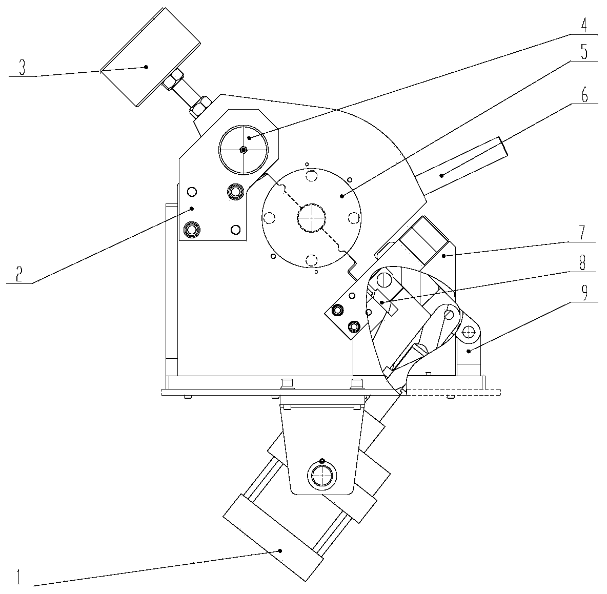
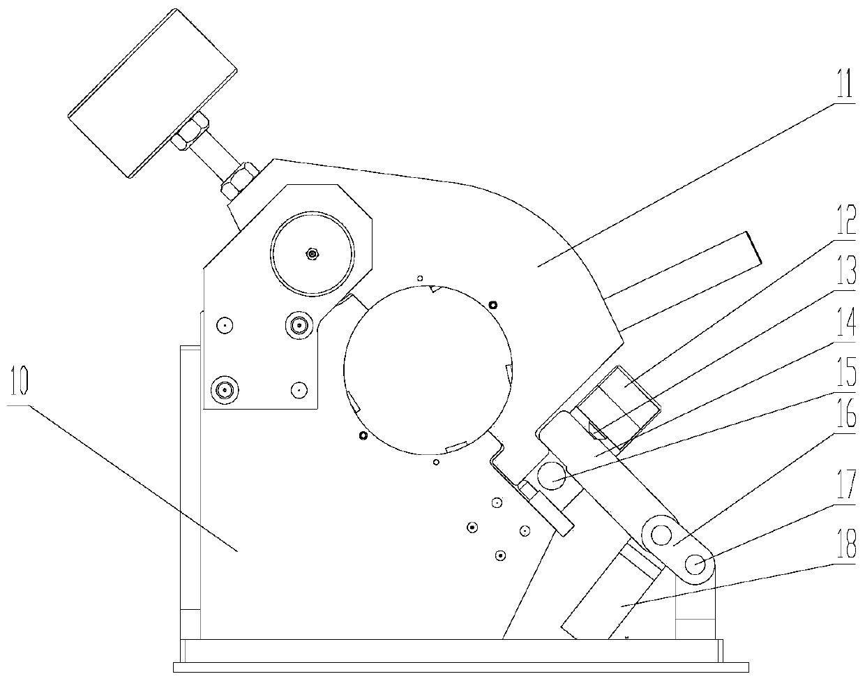
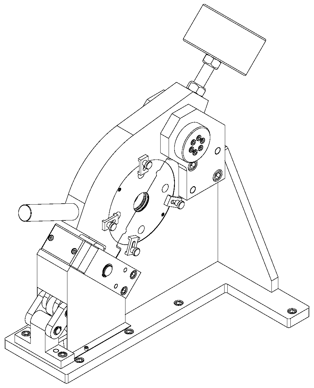
[0023] The pipe fitting clamping mechanism includes a clamping assembly and a locking assembly. The clamping assembly includes an upper mold base 11 and a lower mold base 10 for clamping and fixing the pipe fittings. The upper mold base 11 can be opened and closed around the rotating shaft, and the locking assembly Set on the open and close ends of the lower mold base 10, including:

[0024] The travel switch 8 arranged on the lower die base 10 is used to monitor the opening and closing state of the upper die base 11, and the monitoring head of the tra...


PUM


Abstract

The invention discloses a clamping mechanism for a pipe fitting. The clamping mechanism comprises a clamping assembly and a locking assembly, wherein the clamping assembly comprises an upper mold baseand a lower mold base, the locking assembly is arranged at the opening and closing end of the lower mold base, a travel switch is used for monitoring the opening and closing state of the upper mold base, a limiting mechanism comprises a limiting plate, a limiting post and an adjusting screw, a bolt mechanism comprises a bolt, which slides between the limiting post of the limiting mechanism and the adjusting screw, and the rear end of the bolt is vertically hinged with a cylinder drive shaft and simultaneously hinged with a rotating arm . According to the invention, the opening and closing movement of the bolt adopts a structure that is vertically hinged with the transmission shaft and hinged with the rotating arm, and moves in an adjustable limiting mechanism. When the bolt is opened, a vertical transmission structure is adopted, the front end of the bolt adopts a lifting movement method so as to avoid the skipping movement occurring in the conventional backward opening, and the opening and release are stable and safe; the bolt moves in the limiting mechanism, the locking state of the bolt can be adjusted by adjusting the adjusting screw, and different pipe fittings are more convenient to lock and fix.

Description

technical field [0001] The invention belongs to the technical field of mechanical design, in particular to the technical field of fastening device design, in particular to the design of a clamping mechanism for pipe fittings. Background technique [0002] The pipe fittings are usually clamped and fixed by clamping two mold components, and the upper and lower mold components are also locked to lock the pipe fittings after clamping. In the existing clamping mechanism, manual operations are mostly used to complete, including pipe fittings in place, clamping module clamping, module locking, etc.; there are safety risks in the operation process and damage to pipe fittings due to inability to accurately control the locking ; At the same time, after the existing locking mechanism adopts the automatic locking structure, the clamping module often jumps due to the opening of the dead bolt, and there is an operation safety risk. Contents of the invention [0003] According to the sh...

Claims


Application Information

Patent Timeline
Patent Type & Authority Applications(China)
IPC IPC(8): B25B11/00
CPCB25B11/00
Inventor 王双飞吴海东魏泽锐
Owner SICHUAN ZHONGZI TECH
Learn More