


Quick Research
Generate reliable direction feasibility study reports for your R&D in just a few steps.

Technical Q&A
Discover and master advanced knowledge NOW. Basics, ideas, possibilities, all at once.

Find Solutions
As an expert in R&D theories, this can generate solutions to your technical problems instantly.

Evaluate Feasibility
Analyze your overall solution with one click, know your potential R&D risks in advance.

Monitor Landscape
Get weekly tech updates, stay abreast of the latest tech innovations and key insights.
Automatic burr grinding device for mechanical accessories
A technology for mechanical accessories and grinding, which is used in grinding/polishing safety devices, parts of grinding machine tools, grinding machines, etc. It can solve problems such as inconvenience and automatic loading and unloading, so as to achieve comprehensive grinding, avoid human injury, and automate high degree of effect
- Summary
- Abstract
- Description
- Claims
- Application Information
AI Technical Summary
Problems solved by technology
Method used
Image

Examples
Embodiment 1
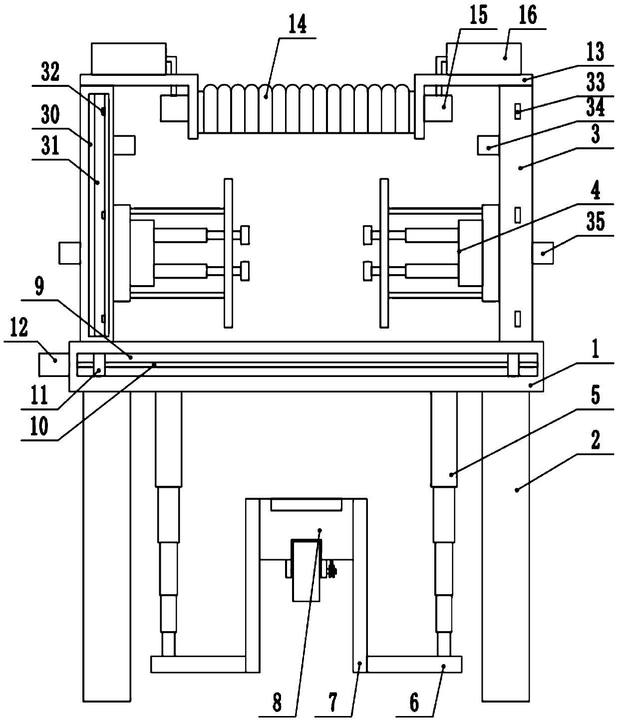
[0024] see Figure 1-3 , an automatic roughening device for mechanical parts, comprising a workbench 1, the four corners of the bottom end of the workbench 1 are fixedly connected to support legs 2, and both ends of the top of the workbench 1 are provided with side plates 3, and the side plates 3 are connected to the workbench 1 Sliding connection, the adjacent sides of the two side plates 3 are equipped with a compression grinding device 4, the top between the two side plates 3 is equipped with an air purification device, and both ends of the bottom of the workbench 1 are fixedly connected to the first The telescopic rod 5, the bottom end of the first telescopic rod 5 is fixedly connected to the pull plate 6, the top of the pull plate 6 is fixedly connected to the fixed plate 7, and a feeding polishing device 8 is arranged between the two fixed plates 7, and the side of the side plate 3 The side is provided with a shielding mechanism, and the side of the workbench 1 is provid...
Embodiment 2
[0034] see Figure 1-3 , the other content of this embodiment is the same as that of Embodiment 1, the difference is that: the shielding mechanism includes a storage groove 30 opened on the side of one of the side plates 3, and the storage groove 30 is connected to the rewinding shaft in rotation, and the rewinding shaft is connected to the side plate 3. The joint of the plate 3 is provided with a clockwork spring, and the outside of the winding shaft is fixedly connected to the curtain 31, and the curtain 31 is wound on the winding shaft, and the end of the curtain 31 away from the winding shaft is fixedly connected to the hook 32, and the side of the other side plate 3 A hanging ring 33 corresponding to the hook 32 is fixedly provided.
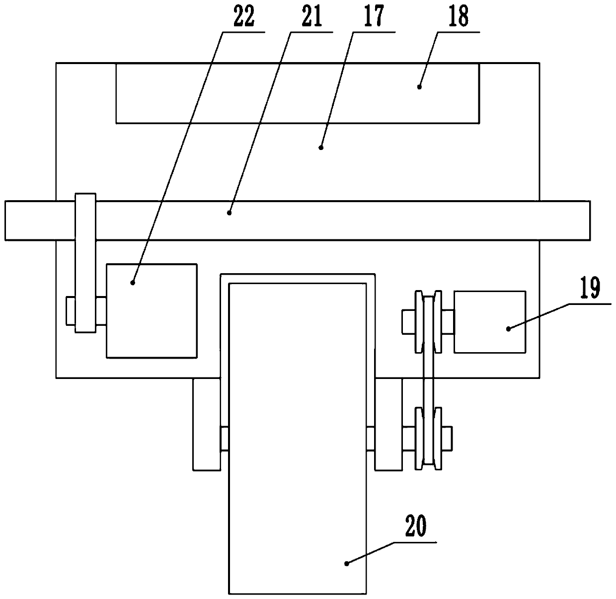
[0035] In the implementation process of the present invention, at first the workpiece to be polished is placed in the placement groove 18, then the first telescopic rod 5 is contracted to send the workpiece between the two compression grindi...
PUM
 Abstract
Description
Claims
Application Information
 - R&D Engineer
- R&D Manager
- IP Professional
- Industry Leading Data Capabilities
- Powerful AI technology
- Patent DNA Extraction
Browse by: Latest US Patents, China's latest patents, Technical Efficacy Thesaurus, Application Domain, Technology Topic, Popular Technical Reports.
© 2024 PatSnap. All rights reserved.Legal|Privacy policy|Modern Slavery Act Transparency Statement|Sitemap|About US| Contact US: help@patsnap.com