
Special-shaped group hole electrolytic machining special machine distributed in circular array

A circular array and special-shaped technology, applied in the field of special-shaped electrolytic machining of group holes, can solve the problems of large thermal shock in the processing area, large consumption of tool electrodes, large differences in efficiency and processing costs, etc., to achieve efficient processing and ensure accuracy. Effect

Active Publication Date: 2020-06-19
HUAIYIN INSTITUTE OF TECHNOLOGY
View PDF7 Cites 1 Cited by
  • Summary
  • Abstract
  • Description
  • Claims
  • Application Information

AI Technical Summary

Problems solved by technology

However, the efficiency and processing cost of different processing methods vary greatly.
The processing of mechanical drilling requires sequential processing of single holes, and its efficiency is too low. If there are dozens or hundreds of holes on the surface of the part, the processing speed will be unbearable, not to mention the complexity and complexity of mechanical drilling for special-shaped holes. Difficulty; special-shaped holes can be processed by EDM, but the tool electrode consumes a lot, and the high temperature of the arc causes a large change in the performance of the processing area of ​​the part
The laser processing method is also a sequential processing of single holes, the thermal shock of the processing area is very large, and even its physical properties are changed

Method used


Image

  • Special-shaped group hole electrolytic machining special machine distributed in circular array
  • Special-shaped group hole electrolytic machining special machine distributed in circular array
  • Special-shaped group hole electrolytic machining special machine distributed in circular array

Examples


Embodiment Construction

[0029] The following will clearly and completely describe the technical solutions in the embodiments of the present invention in conjunction with the accompanying drawings in the embodiments. Obviously, the described embodiments are only part of the embodiments of the present invention, not all of them. Based on the embodiments of the present invention, all other embodiments obtained by persons of ordinary skill in the art without making creative efforts belong to the protection scope of the present invention.

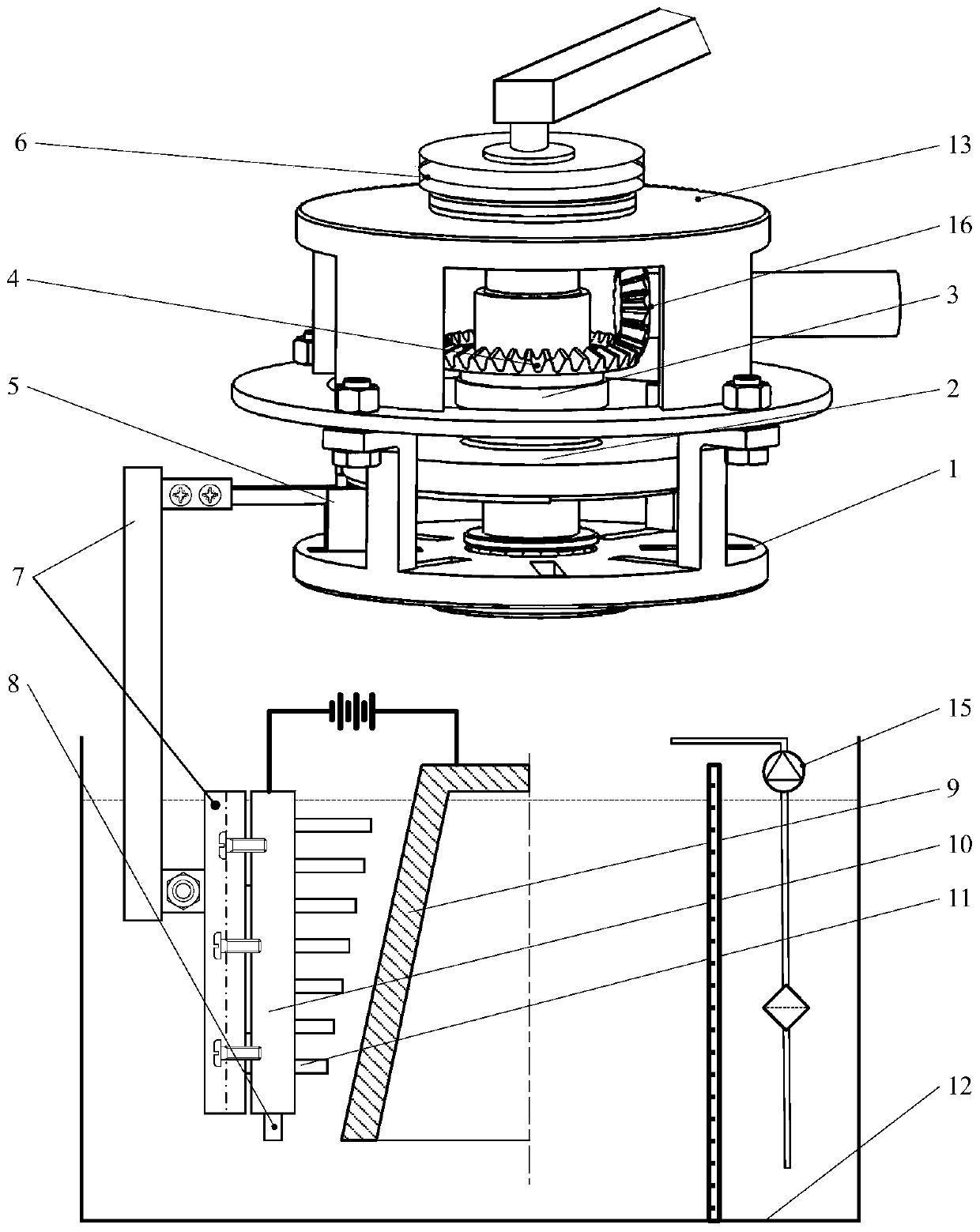
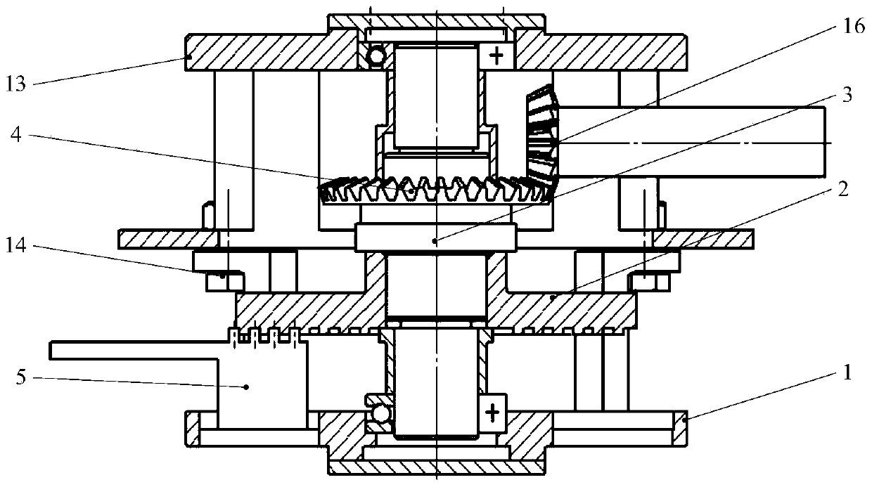
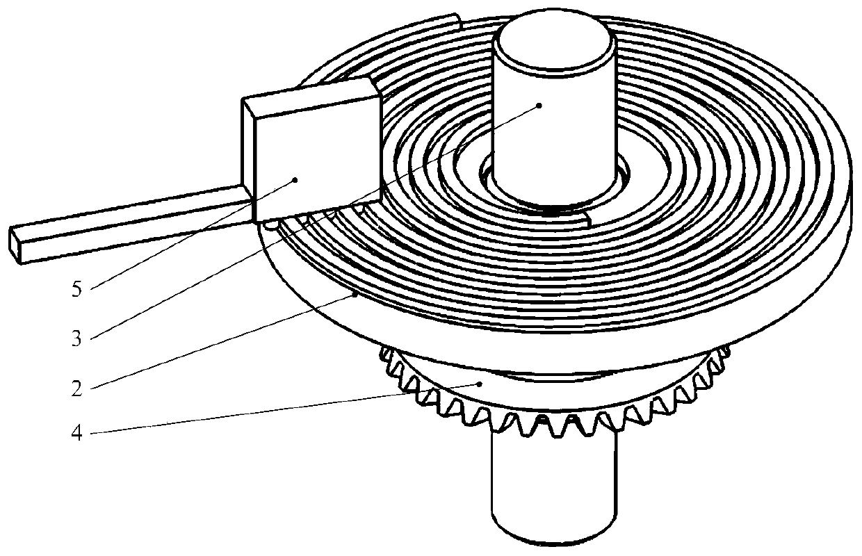
[0030] Such as Figure 1-3 As shown, the special-shaped electrolytic machining machine with group holes distributed in a circular array includes:

[0031] Box 13;

[0032] A motion limiting disc 1, which is located below the box body and fixedly connected with the box body, and has an array of guide grooves on the motion limiting disc;

[0033] Shaft 3, the two ends of the shaft are installed on the motion limiting disc and the box through bearings;

[0034] Drive d...


PUM


Abstract

The invention provides a special-shaped group hole electrolytic machining special machine distributed in a circular array. The special-shaped group hole electrolytic machining special machine comprises a box, a movement limiting disk, a shaft, a driving disk, an electrode driving arm, a gear A, a gear B and a working fluid tank, wherein a groove is formed in the movement limiting disk; a vortex groove is formed in the lower end surface of the driving disk; the electrode driving arm is connected with a tool electrode device for mounting an electrode; the upper end of the electrode drive arm isprovided with engagement teeth; the electrode drive arm is placed in the groove and is engaged with the driving disk; the gear A is fixedly installed on the shaft; the gear B is fixedly installed on an input shaft; and the gear B is engaged with the gear A. Through the design of the vortex groove and the engagement teeth, the electrode drive arm is engaged with the driving disk; when power is input to the input shaft, the top of the electrode drive arm is limited by the driving disk and the two sides of the electrode drive arm are limited by guide grooves in the movement limiting disk; and theelectrode drive arm can only perform radial movement in the guide grooves. The special-shaped group hole electrolytic machining special machine adopting the scheme has the advantage that the electrode array does not produce circumferential and vertical displacement, and the accuracy of the process action is ensured.

Description

technical field [0001] The invention relates to a special-shaped electrolytic machining machine with a group of holes distributed in a circular array, which belongs to the technical field of electrochemical machining. Background technique [0002] There are many methods for machining irregular-shaped group holes distributed in a circular array. However, the efficiency and processing cost of different processing methods vary greatly. The processing of mechanical drilling requires sequential processing of single holes, and its efficiency is too low. If there are dozens or hundreds of holes on the surface of the part, the processing speed will be unbearable, not to mention the complexity and complexity of mechanical drilling for special-shaped holes. Difficulty: Special-shaped holes can be processed by EDM, but the tool electrode consumes a lot, and the high temperature of the arc causes a large change in the performance of the part processing area. The laser processing metho...

Claims


Application Information

Patent Timeline
IPC IPC(8): B23H3/00B23H7/30B23H9/14
CPCB23H3/00B23H7/30B23H9/14
Inventor 郑晓虎谷洲之
Owner HUAIYIN INSTITUTE OF TECHNOLOGY
Learn More