Eureka AIR delivers breakthrough ideas for toughest innovation challenges, trusted by R&D personnel around the world.

Battery cell tab connecting structure, soft package battery, electric equipment, electric vehicle and power station

A technology for connecting structures and electrical equipment, applied in secondary batteries, structural parts, battery pack parts, etc., can solve the problems of detecting welding quality, reducing the flow area of ​​busbars, easy separation, etc. The effect of avoiding virtual welding and facilitating the detection of welding quality

Pending Publication Date: 2020-06-16
四川国创成电池材料有限公司
View PDF0 Cites 4 Cited by
  • Summary
  • Abstract
  • Description
  • Claims
  • Application Information

AI Technical Summary

Problems solved by technology

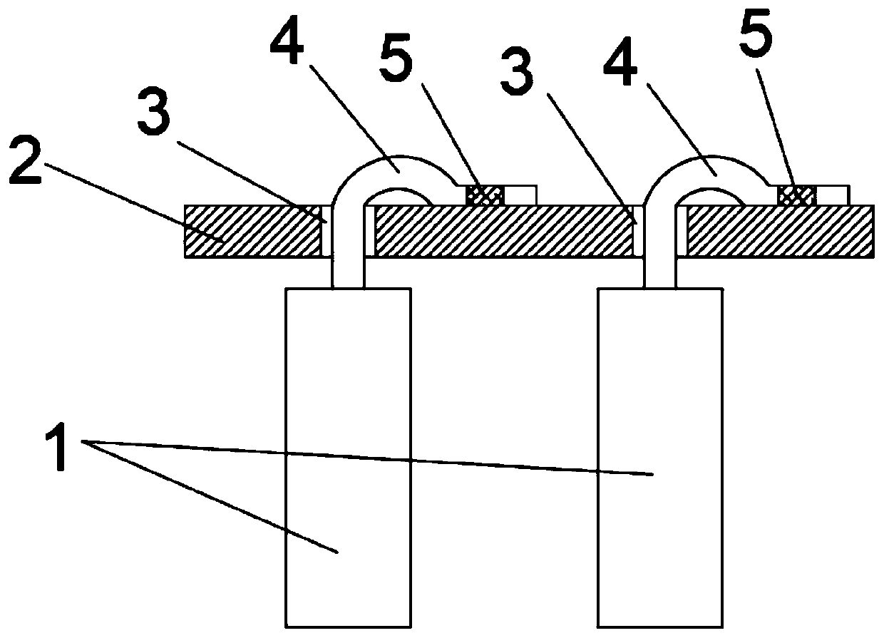
The main problems of existing laser welding are: 1. There is a gap between the tab and the through hole of the bus bar, which reduces the effective flow area of ​​the bus bar; 2. After the tab is bent, it is pressed on the top of the bus bar. Since the tab is made of metal, the metal has elasticity after bending, and the tab has a tendency to rebound. After the tab is bent, there is a gap between the side facing the bus bar and the bus bar. During laser welding, there may be a gap between the tab and the bus Insufficient bonding of the row leads to false welding, and the tab and the bus bar are easily separated after welding; 3. The laser irradiates the tab from the top of the bent tab to the bottom of the tab, so that the tab is welded to the bus bar below. The welding seam between the tab and the bus bar is on the surface of the tab facing the bus bar. The weld seam is blocked by the tab, and the welding quality cannot be detected by common appearance inspection methods after welding.

Method used


Image

  • Battery cell tab connecting structure, soft package battery, electric equipment, electric vehicle and power station
  • Battery cell tab connecting structure, soft package battery, electric equipment, electric vehicle and power station
  • Battery cell tab connecting structure, soft package battery, electric equipment, electric vehicle and power station

Examples


Embodiment Construction

[0029] In order to make the object, technical solution and advantages of the present invention clearer, the present invention will be further described in detail below in conjunction with the accompanying drawings.

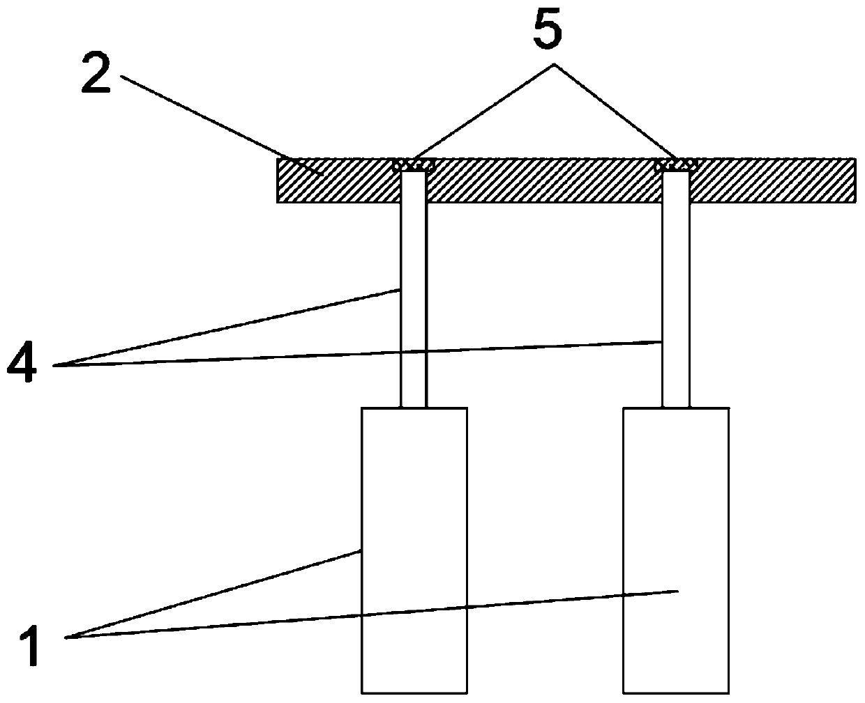
[0030] Such as Figure 1-Figure 4 As shown, the embodiment of the battery lug connection structure disclosed in the present invention includes a tab 4 and a bus bar 2. The bus bar 2 has a through hole 3 adapted to the tab 4, and the through hole 3 corresponds to the tab 4. Setting, one end of the tab 4 is connected to the cell 1, the other end of the tab 4 is inserted into the corresponding through hole 3 on the bus bar 2, the tab 4 is not bent, and the tab 4 and the bus bar 2 are at the through hole 3 Joined by laser welding.

[0031] The end of the tab 4 away from the cell 1 is flush with the side of the bus bar 2 away from the cell 1, and the end of the tab 4 away from the cell 1 and the side of the bus bar 2 away from the cell 1 are at the corresponding throu...


PUM


Abstract

The invention discloses a battery cell tab connecting structure which comprises tabs and busbars. Through holes matching the tabs are formed in the busbars; the through holes correspond to the tabs; one end of each tab is connected with a battery cell, and the other end of the tab is inserted into the corresponding through hole in a busbar; the tabs and the busbars are connected through laser welding at the through holes. The invention further provides a soft package battery which comprises the battery cell tab connection structure, electric equipment, an electric vehicle and a power station. According to the battery cell tab connecting structure, the soft package battery, the electric equipment, the electric vehicle and the power station, which are provided by the invention, the busbarover-current area is not occupied; the busbars and the tabs are firmly welded; pseudo soldering can be avoided; and the welding quality is convenient to detect.

Description

technical field [0001] The invention relates to the field of batteries, in particular to a battery tab connection structure, a pouch battery, electrical equipment, an electric vehicle and a power station. Background technique [0002] Lithium-ion batteries have the advantages of large battery capacity and small size. Lithium-ion batteries often include several pouch battery modules, and pouch batteries are formed by connecting multiple cells in series and parallel through tabs. Or laser welding method to connect, using bolt connection is easy to cause short circuit, and requires a large number of bolts, which greatly increases the weight of the pouch battery; using ultrasonic welding connection, it is necessary to reserve a large amount on both sides of the tab to be welded The space for the clamping part to clamp the tab, and it is not convenient for multiple tabs to be connected at the same place. The most commonly used method is laser welding. [0003] Such as figure ...

Claims


Application Information

Patent Timeline
IPC IPC(8): H01M2/26H01M10/0525
CPCH01M10/0525H01M50/531Y02E60/10
Inventor 胡蕴成杨烨吴天文孙滋夏王睿王珂王荣贵
Owner 四川国创成电池材料有限公司
Why Eureka
Eureka Blog
Learn More