
Display panel and preparation method thereof

A display panel and plate technology, applied in semiconductor/solid-state device manufacturing, organic semiconductor devices, electrical components, etc., can solve the problems of thin film transistor device functions that cannot be achieved, active layer film thickness, contact resistance damage, source, Problems such as the inability of the drain and the active layer to conduct, achieve the effects of mass production, improved conduction characteristics, and increased edge contact paths

Active Publication Date: 2020-06-16
SHENZHEN CHINA STAR OPTOELECTRONICS SEMICON DISPLAY TECH CO LTD
View PDF6 Cites 2 Cited by
  • Summary
  • Abstract
  • Description
  • Claims
  • Application Information

AI Technical Summary

Problems solved by technology

[0004] An embodiment of the present invention provides a display panel, which is used to solve the problem of the display panel in the prior art. Since the source, gate and drain are prepared in the same layer, during the wet etching process, the metal etchant and the active layer Continuous contact will cause severe damage to the film thickness and contact resistance of the active layer, resulting in the inability of the source, drain and active layer to conduct, resulting in a technical problem that the function of the thin film transistor device cannot be achieved.

Method used


Image

  • Display panel and preparation method thereof
  • Display panel and preparation method thereof
  • Display panel and preparation method thereof

Examples


Embodiment Construction

[0022] The following will clearly and completely describe the technical solutions in the embodiments of the present invention with reference to the accompanying drawings in the embodiments of the present invention. Obviously, the described embodiments are only some, not all, embodiments of the present invention. Based on the embodiments of the present invention, all other embodiments obtained by those skilled in the art without creative efforts fall within the protection scope of the present invention.

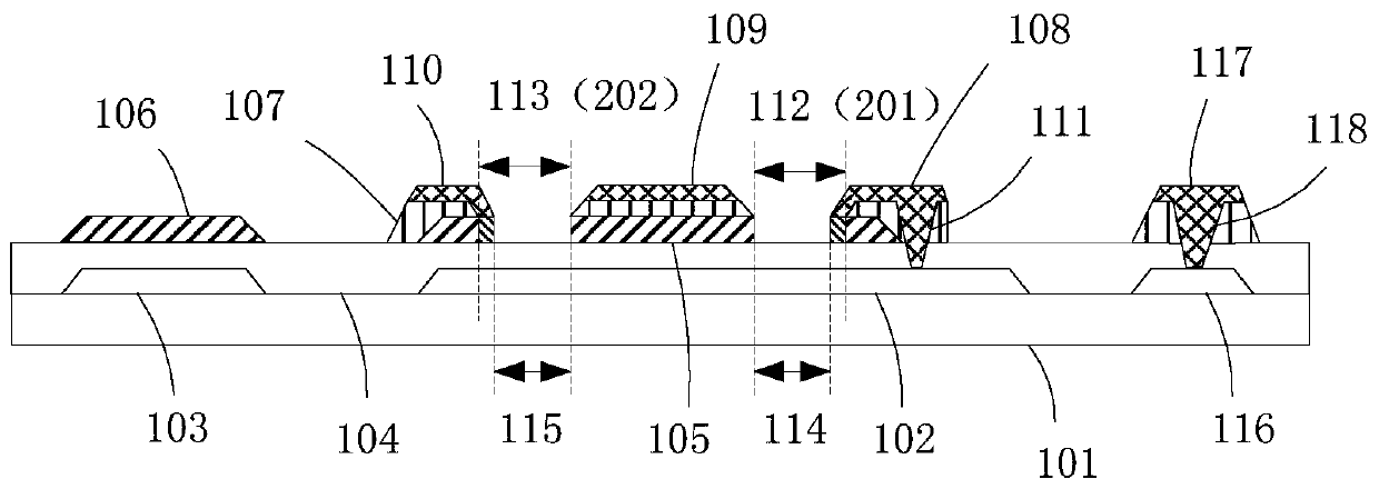
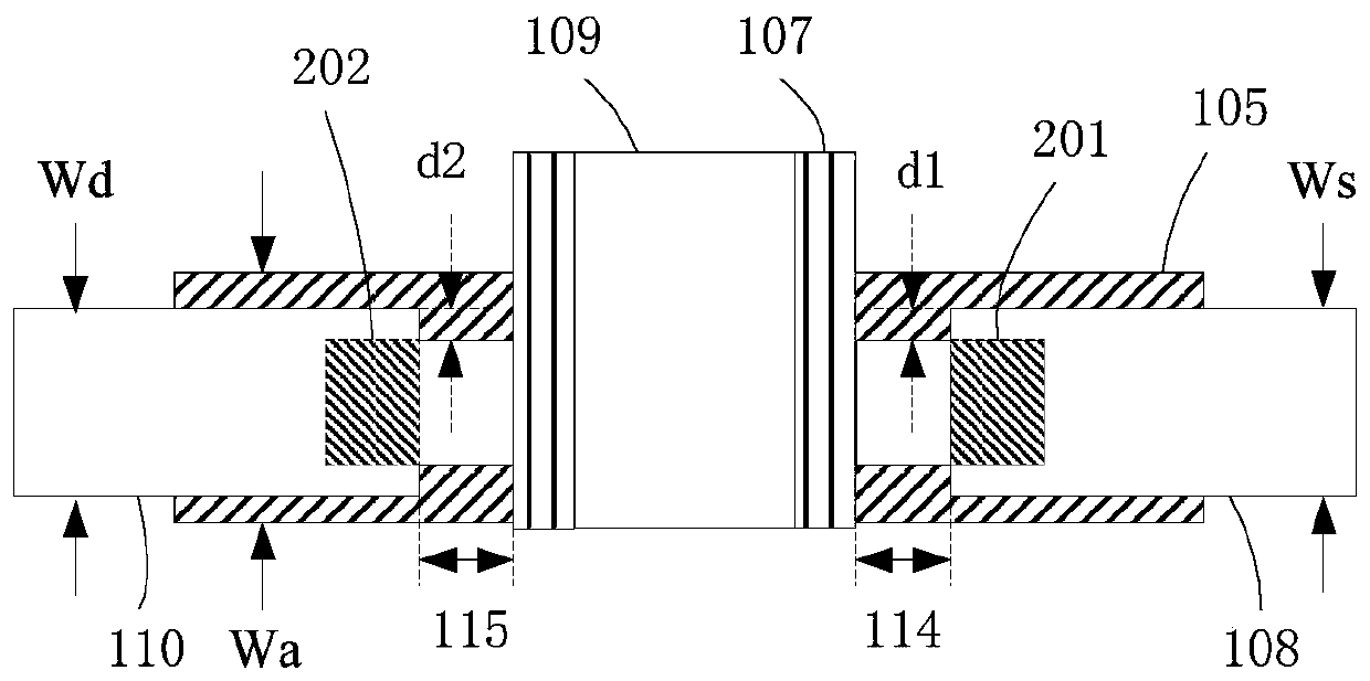
[0023] see figure 1 , the schematic diagram of the basic structure of the display panel provided by Embodiment 1 of the present invention. From the figure, it is possible to intuitively see the various components of the present invention and the relative positional relationship between the various components. The display panel includes a substrate layer 101 , the light-shielding metal layer 102 on the substrate layer 101 and the first plate 103 of the storage capacitor, the bu...


PUM


Abstract

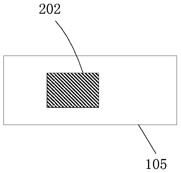
The invention provides a display panel and a preparation method thereof. The display panel comprises a substrate layer, a shading metal layer and the first polar plate of a storage capacitor which arepositioned on the substrate layer, a buffer layer which is located on the substrate layer and covers the shading metal layer and the first polar plate, an active layer and the second polar plate of the storage capacitor which are located on the buffer layer, , a gate insulation layer which is located on the buffer layer and the active layer, and a source electrode, a gate electrode and a drain electrode which are located on the gate insulation layer. The width of the source electrode and the width of the drain electrode are both smaller than the width of the active layer. According to the invention, by increasing the conductor area of the active layer, edge contact paths between the active layer and the source electrode and between the active layer and the drain electrode are increased; the edge contact yield of the source electrode, the drain electrode and the active layer is increased by means of the transverse diffusion phenomenon during conductor of the active layer; and the conduction characteristic of a thin film transistor device is greatly improved.

Description

technical field [0001] The invention relates to the field of display technology, in particular to a display panel and a preparation method thereof. Background technique [0002] At present, the thin film transistor with top gate structure has a complex structure and many layers, which leads to high time cost and material cost, and also brings a certain degree of loss in yield. Therefore, it is necessary to develop a top gate with reduced manufacturing process and better device functions. thin film transistor. [0003] The existing technology uses a new process of preparing the source, gate and drain in the same layer to prepare the display panel. Compared with the original top-gate structure of the thin film transistor process, it saves a metal film formation, photolithography, etching and interlayer. The insulating layer greatly saves the cost, but due to the large difference in the manufacturing process of the original top-gate thin-film transistor, especially the active ...

Claims


Application Information

Patent Timeline
Patent Type & Authority Applications(China)
IPC IPC(8): H01L27/12H01L21/77H01L27/32
CPCH01L27/1222H01L27/1225H01L27/1255H01L27/1259H01L27/127H01L21/77H10K59/1213H10K59/1201H10K71/00H10K59/873H01L29/41733H01L29/78633H10K59/1216H10K59/126H01L29/78618H10K50/844H10K59/122H10K59/124H10K2102/103
Inventor 唐甲
Owner SHENZHEN CHINA STAR OPTOELECTRONICS SEMICON DISPLAY TECH CO LTD
Learn More