
Reciprocating motion loading test system for testing roadbed and pavement deformation and test method thereof

A reciprocating movement and loading test technology, which is applied in the field of traffic engineering, can solve the problems of not considering the influence of water on the performance of roadbed pavement, thickness reduction, boundary condition restrictions, etc.

Active Publication Date: 2020-06-16
CHANGSHA UNIVERSITY OF SCIENCE AND TECHNOLOGY
View PDF8 Cites 1 Cited by
  • Summary
  • Abstract
  • Description
  • Claims
  • Application Information

AI Technical Summary

Problems solved by technology

[0004] 1. The above two methods do not consider the influence of water on the performance of the subgrade and pavement. Different groundwater levels and different rainfall conditions will affect the overall force of the subgrade and pavement and the strength of the soil, which in turn will affect the deformation of the subgrade and pavement.
[0005] 2. Conventional triaxial tests must make the pavement subgrade into a cylindrical sample, the boundary conditions are limited, and the thickness cannot be restored according to the actual engineering situation
[0006] 3. The conventional triaxial test does not consider the reciprocating movement of the vehicle and the impact of the vehicle's acceleration and deceleration process on the subgrade and road surface
[0008] 5. The above two methods do not take into account the impact of the acceleration of the object on the vehicle on the force of the vehicle

Method used


Image

  • Reciprocating motion loading test system for testing roadbed and pavement deformation and test method thereof
  • Reciprocating motion loading test system for testing roadbed and pavement deformation and test method thereof
  • Reciprocating motion loading test system for testing roadbed and pavement deformation and test method thereof

Examples


Embodiment Construction

[0052] The technical solutions in the embodiments of the present invention will be clearly and completely described below in conjunction with the embodiments of the present invention. Apparently, the described embodiments are only some of the embodiments of the present invention, not all of them. Based on the embodiments of the present invention, all other embodiments obtained by persons of ordinary skill in the art without making creative efforts belong to the protection scope of the present invention.

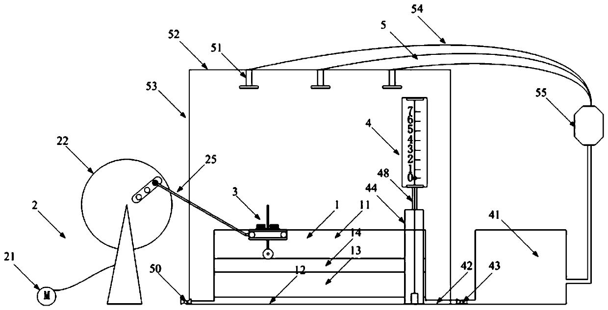
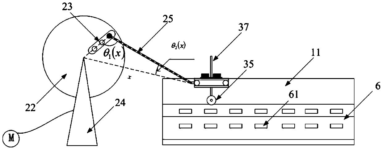
[0053] An embodiment of the present invention is a reciprocating mobile loading test system for testing the deformation of the roadbed and road surface, such as figure 1 As shown, it includes subgrade pavement system 1, driving device 2, mobile wheel load simulation device 3, groundwater level simulation device 4, ground rainfall simulation device 5 and measurement system 6;

[0054] The subgrade and pavement system 1 includes a transparent glass box 11. The base layer 12, th...


PUM


Abstract

The invention discloses a reciprocating motion loading test system for testing roadbed and pavement deformation and a test method thereof. The test system comprises a roadbed and pavement system, a driving device, a moving wheel load simulation device and a measurement system, wherein the driving device comprises a rotating disc, and a clamping groove is formed in the radius direction of the rotating disc; the moving wheel load simulation device comprises a loading wheel, the loading wheel is in contact with the pavement-roadbed structure model, a horizontally-arranged top plate is installed above the loading wheel, the middle of a shaft of the loading wheel is fixedly connected with the top plate through a loading shaft, a bearing disc is installed on the top plate, weights are placed onthe bearing disc, a rotary support is arranged at the end, close to the driving device, of the top plate and hinged to one end of a connecting rod through a bolt, and the other end of the connecting rod is connected with a hinge hole in the clamping groove. The driving device and the moving wheel load simulation device form a power loading system, the real state of vehicle advancing is simulated to a higher degree, and the accuracy of predicting roadbed and pavement deformation under the vehicle load effect is improved.

Description

technical field [0001] The invention belongs to the technical field of traffic engineering, and relates to a reciprocating mobile loading test system and a test method for testing roadbed and road surface deformation. Background technique [0002] With the rapid development of the national economy, the volume of road goods and passengers has increased significantly, and the phenomena of large vehicles and heavy loads have emerged in an endless stream. Heavy-duty vehicles pose great challenges to the bearing capacity of the subgrade and the shear strength of the road surface due to their large size, fast speed and large number. Under heavy traffic conditions, the uneven settlement of the subgrade is intensified, and ruts and cracks occur in the wheel tracks of the road surface. At the same time, water also has great harm to the roadbed and pavement. Surface water scours the road surface, causing water damage, and water seeps into the roadbed, making the roadbed soil too wet...

Claims


Application Information

Patent Timeline
IPC IPC(8): G01N3/34G01N3/02
CPCG01N3/34G01N3/02G01N2203/0005G01N2203/0037G01N2203/0062G01N2203/0066G01N2203/0246G01N2203/0682
Inventor 邱祥黎繁蒋煌斌付宏渊
Owner CHANGSHA UNIVERSITY OF SCIENCE AND TECHNOLOGY
Learn More