


Quick Research
Generate reliable direction feasibility study reports for your R&D in just a few steps.

Technical Q&A
Discover and master advanced knowledge NOW. Basics, ideas, possibilities, all at once.

Find Solutions
As an expert in R&D theories, this can generate solutions to your technical problems instantly.

Evaluate Feasibility
Analyze your overall solution with one click, know your potential R&D risks in advance.

Monitor Landscape
Get weekly tech updates, stay abreast of the latest tech innovations and key insights.
Detection device for pipe fitting production
A detection device and pipe fitting technology, applied in the direction of mechanical roughness/irregularity measurement, etc., can solve the problems of U-shaped pipe slippage, influence of U-shaped pipe end face detection data, etc., to prevent damage and facilitate detection and processing.
- Summary
- Abstract
- Description
- Claims
- Application Information
AI Technical Summary
Problems solved by technology
Method used
Image

Examples
Embodiment 1
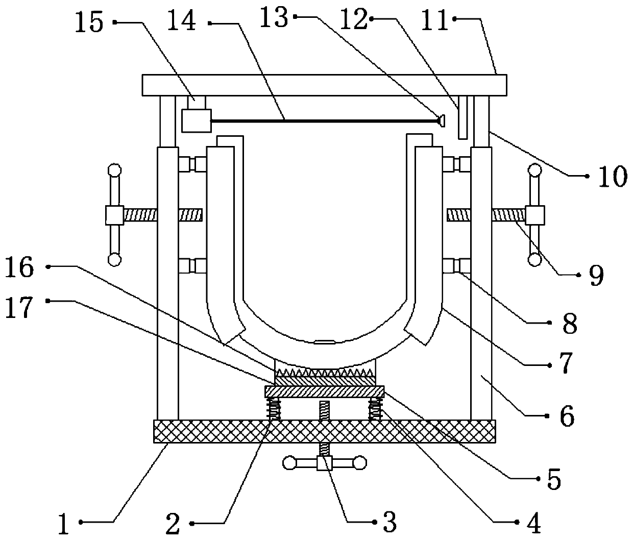
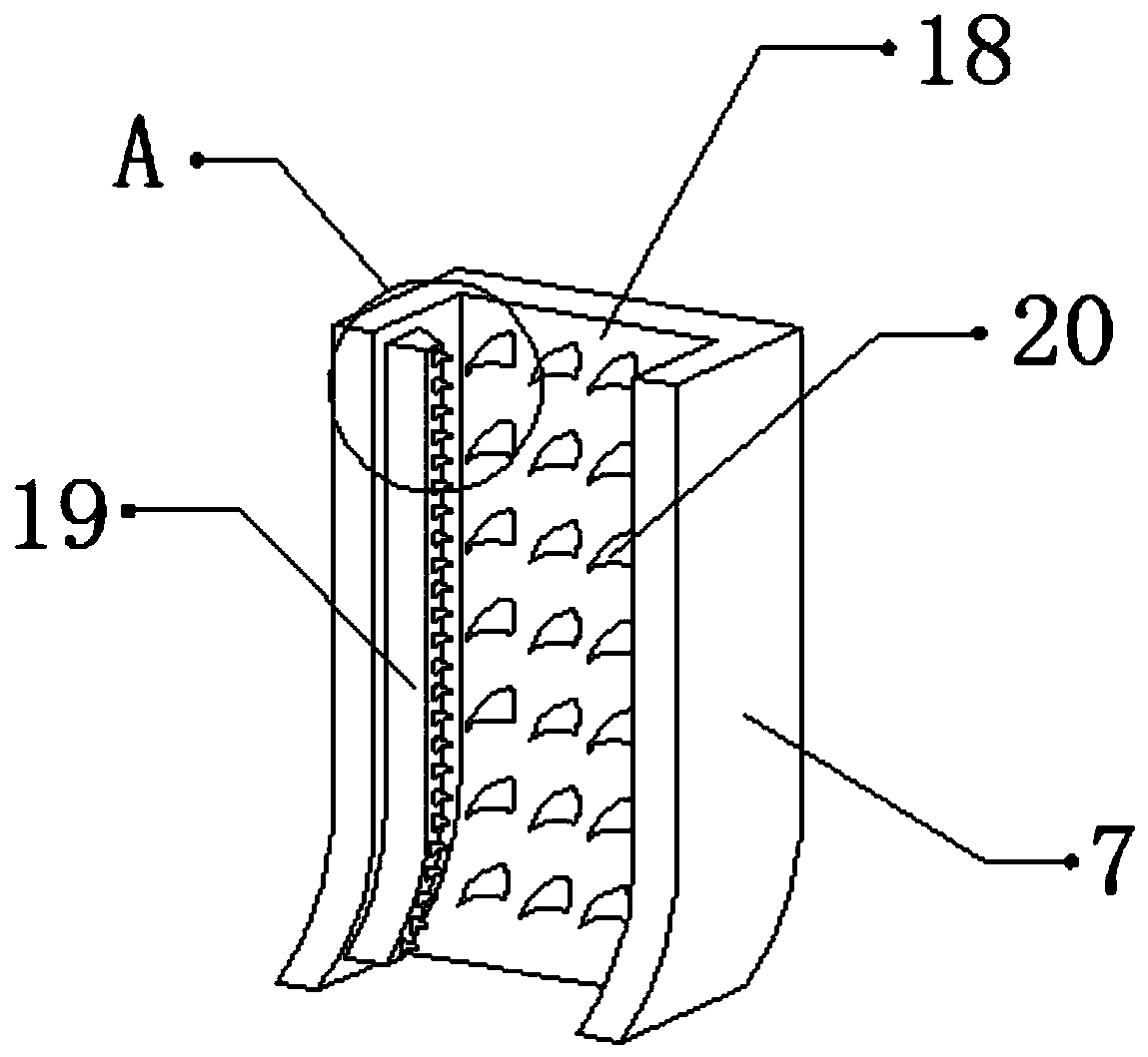
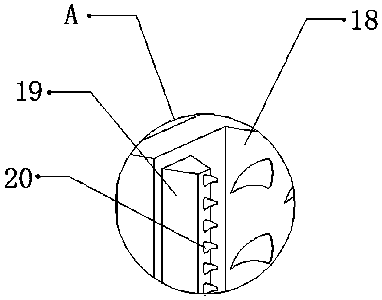
[0028] refer to Figure 1-3 , a detection device for the production of pipe fittings, comprising a fixed seat 1, the two sides of the top outer wall of the fixed seat 1 are connected with fixed rods 6 by bolts, and the outer walls of the opposite side of the two fixed rods 6 are connected with two second fixed rods by bolts. Two telescopic rods 8, one side outer wall of the second telescopic rod 8 is connected with splint 7 by bolt, and the opposite side outer walls of two splints 7 are all provided with fixed groove 18, and the opposite side inner wall of fixed groove 18 is bonded with constraint plate 19, and one side of the outer wall of the constraining plate 19 and one side of the inner wall of the fixing groove 18 are provided with a plurality of equidistantly distributed protruding teeth 20, the shape of the protruding teeth 20 is canine, and the top outer walls of the two fixing rods 6 pass through Bolts are connected with fixed shafts 10, and the top outer walls of th...
Embodiment 2
[0032] refer to Figure 4 , a detection device for the production of pipe fittings. Compared with Embodiment 1, in this embodiment, the outer walls on the opposite side of the two fixed rods 6 are connected with a second spring 21 by bolts, and the outer wall on one side of the second spring 21 is connected to the splint 7 are connected by bolts, and the restorability of the second spring 21 can prevent the splint 7 from causing damage to the surface of the U-shaped tube due to the strong clamping force of the U-shaped tube.
[0033] Working principle: when in use, place the U-shaped tube that needs to be detected and processed inside the fixing frame 17, fix the bottom of the U-shaped tube through the fastening bolt, and at the same time, turn the second threaded rod 9 to make the second threaded rod 9 drives the splint 7 to move, so that the splint 7 is clamped and fixed, and the friction force between the U-shaped tube and the splint 7 can be increased through the restraint...
PUM
 Abstract
Description
Claims
Application Information
 - R&D Engineer
- R&D Manager
- IP Professional
- Industry Leading Data Capabilities
- Powerful AI technology
- Patent DNA Extraction
Browse by: Latest US Patents, China's latest patents, Technical Efficacy Thesaurus, Application Domain, Technology Topic, Popular Technical Reports.
© 2024 PatSnap. All rights reserved.Legal|Privacy policy|Modern Slavery Act Transparency Statement|Sitemap|About US| Contact US: help@patsnap.com