Fabric drying device for textile industry

A technology for fabric drying and textile industry, applied in drying, dryer, drying gas arrangement and other directions, can solve problems such as inability to guarantee fabric and heat source, uneven heating of fabric, affecting drying effect, etc., to achieve flexible use , The effect of heating evenly and prolonging the moving time

Inactive Publication Date: 2020-06-16
冯秀则
View PDF7 Cites 2 Cited by
  • Summary
  • Abstract
  • Description
  • Claims
  • Application Information

AI Technical Summary

Problems solved by technology

[0003] At present, the traditional equipment for drying cloth is too large to ensure sufficient contact between the cloth and the heat source, which will easily lead to uneven heating of the cloth and affect the drying effect.

Method used


Image

  • Fabric drying device for textile industry
  • Fabric drying device for textile industry
  • Fabric drying device for textile industry

Examples


Embodiment 1

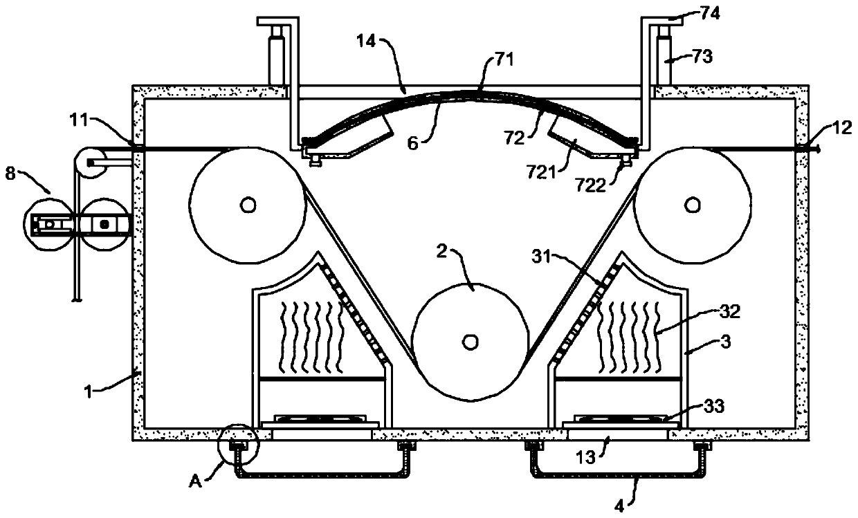
[0023] see Figure 1~3 , in an embodiment of the present invention, a fabric drying device for the textile industry, comprising a box body 1 and a drying mechanism arranged in the box body 1; the box body 1 is provided with conveying rollers 2 arranged in a triangle, and the box body 1 The two side shell walls of the body 1 are symmetrically provided with an inlet 11 and an outlet 12 for the cloth to enter and exit. During the working process, the cloth moves in the box body 1, and the conveying rollers 2 arranged in a triangle enable the cloth to travel along the folding line and extend its length. Movement time in box 1.

[0024] The drying mechanism includes a heat source frame 3 and a fan 33, wherein the heat source frame 3 is fixed on the inner wall of the box body 1 and covers the air inlet 13 provided on the casing wall of the box body 1. The heat source frame 3 An electric heating wire 32 is installed inside, and the heat source frame 3 has an inclined plane parallel ...

Embodiment 2

[0033] see figure 1 and 4 , the difference between the embodiment of the present invention and embodiment 1 is:

[0034] In this embodiment, an extruding mechanism 8 is also included. The extruding mechanism 8 is arranged on the outer wall of the box body 1 at a position corresponding to the inlet 11. The extruding mechanism 8 includes an installation frame 81 and is arranged symmetrically in the installation frame 81. The arranged extrusion roller squeezes the cloth by the extrusion roller, thereby extruding the moisture on the cloth, so that the cloth can be dried faster after entering the box body 1 .

[0035]Further, the squeeze roller includes a movable roller 82 and a fixed roller 83, wherein the movable roller 82 is mounted on a movable seat 85 slidably connected to the mounting frame 81, and the fixed roller 83 is mounted on a fixed seat fixed to the mounting frame 81 84, a telescopic device 86 is also installed on the inner frame surface of the installation frame 81...


PUM


Abstract

The invention discloses a fabric drying device for the textile industry. The fabric drying device for the textile industry comprises a box and a drying mechanism arranged in the box. Conveying rollersdistributed in a triangular shape are arranged in the box, and an inlet and an outlet are symmetrically formed in the two side shell walls of the box and are used for feeding and discharging fabric.The drying mechanism comprises a heat source frame and draught fans, wherein the heat source frame is fixed to the inner wall of the box and covers gas inlets formed in the shell wall of the box inside, electric heating wires are installed in the heat source frame, a slope parallel to the advancing track of fabric is arranged on the heat source frame, through holes are evenly distributed in the slope, and the draught fans are installed at the positions, corresponding to the gas inlets, of the inner wall of the box. According to the fabric drying device for the textile industry, the drying mechanism formed by the components of the heat source frame, the draught fans and the like is arranged, as the side, with the through holes, of the heat source frame is parallel to the advancing directionof the fabric, hot gas flow can directly act on the fabric, the fabric can be heated evenly, and the drying effect can be ensured.

Description

technical field [0001] The invention relates to the field related to the textile industry, in particular to a cloth drying device for the textile industry. Background technique [0002] With the development of industry, the textile industry has gradually changed from manual operation to machine operation. Cloth is one of the finished products in the textile industry, and it needs to go through a drying process during processing. [0003] At present, the traditional cloth drying devices are too many to ensure sufficient contact between the cloth and the heat source, which easily leads to uneven heating of the cloth, thereby affecting the drying effect. Contents of the invention [0004] The object of the present invention is to provide a cloth drying device for textile industry to solve the above problems. [0005] To achieve the above object, the present invention provides the following technical solutions: [0006] A cloth drying device for the textile industry, compri...

Claims


Application Information

Patent Timeline
Patent Type & Authority Applications(China)
IPC IPC(8): F26B13/08F26B13/28F26B21/00F26B21/08F26B25/00
CPCF26B13/08F26B13/28F26B21/001F26B21/003F26B21/004F26B21/083F26B25/00F26B25/003
Inventor 冯秀则
Owner 冯秀则
Why Eureka
Try Eureka