
Novel overhanging I-steel pre-embedded anchor device and anchor method

An anchoring device and anchoring method technology, applied in the direction of house structure support, house structure support, scaffolding accessories, etc., can solve the problems of unreliable fixing of I-beams, potential safety hazards, horizontal movement, etc., to change the fastening direction, Improve the anti-torsion ability and the effect of firm fixation

Pending Publication Date: 2020-06-16
ZIBO TECHNICIAN COLLEGE
View PDF0 Cites 1 Cited by
  • Summary
  • Abstract
  • Description
  • Claims
  • Application Information

AI Technical Summary

Problems solved by technology

[0004] This application is to solve the problem that the two ends of the existing cantilevered I-beam are under the action of a force couple, the I-beam is not fixed firmly in the horizontal direction, and there is a problem of horizontal rotation. The fixed outer frame pole moves horizontally, which poses a safety hazard. Therefore, a new type of cantilevered I-beam embedded anchoring device and anchoring method is designed:

Method used


Image

  • Novel overhanging I-steel pre-embedded anchor device and anchor method
  • Novel overhanging I-steel pre-embedded anchor device and anchor method
  • Novel overhanging I-steel pre-embedded anchor device and anchor method

Examples


Embodiment Construction

[0032] In order to clearly illustrate the technical features of this solution, the present invention will be described in detail below through specific implementation methods and in conjunction with the accompanying drawings.

[0033] In addition, in the description of the present invention, it should be understood that the terms "center", "upper", "lower", "front", "rear", "left", "right", "vertical", "horizontal" ", "Top", "Bottom", "Inner", "Outer", "Axial", "Radial", "Circumferential" and other indicated orientations or positional relationships are based on the orientations or positional relationships shown in the drawings , is only for the convenience of describing the present invention and simplifying the description, but does not indicate or imply that the referred device or element must have a specific orientation, be constructed and operated in a specific orientation, and thus should not be construed as limiting the present invention.

[0034] Such as Figure 1-3 As ...


PUM


Abstract

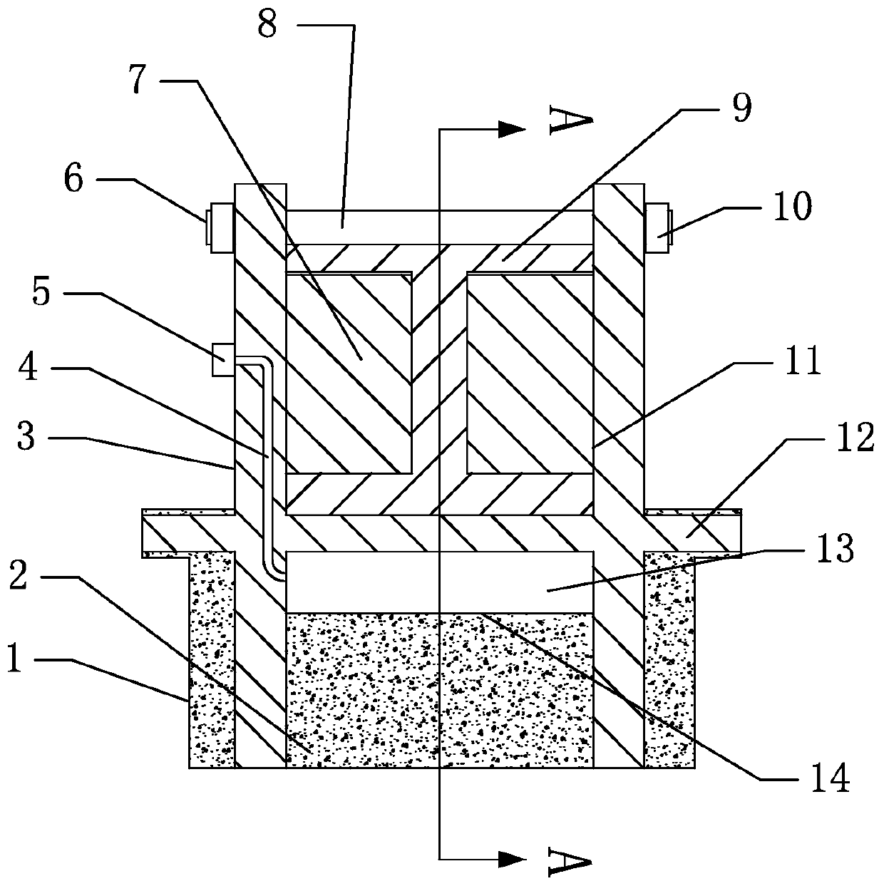
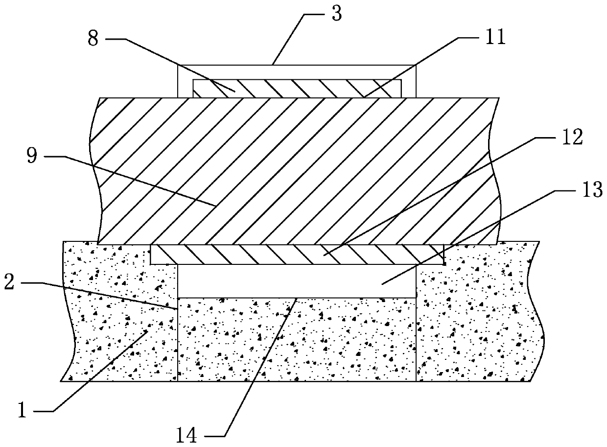
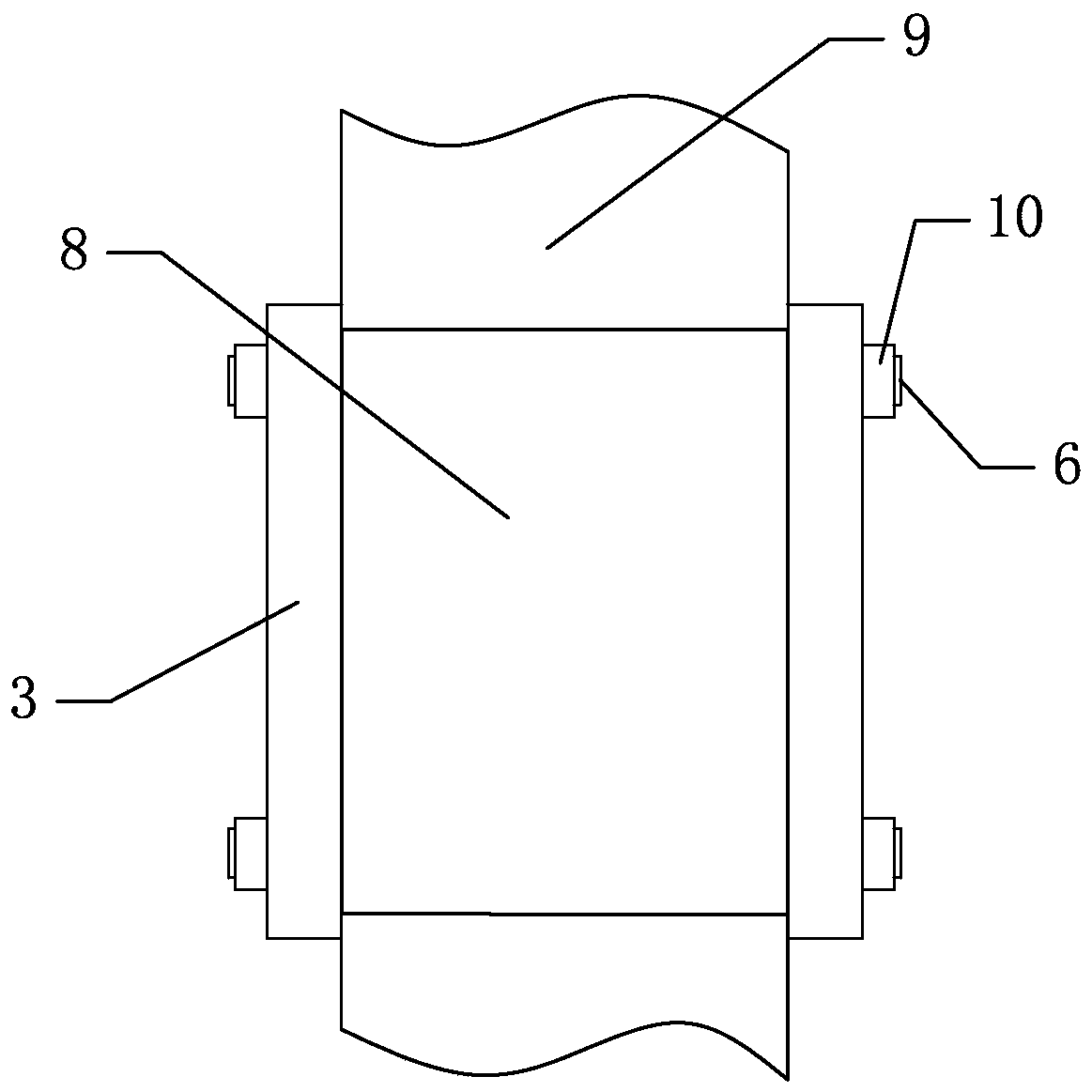
The invention relates to a novel overhanging I-steel pre-embedded anchor device and anchor method, and belongs to the field of constructional engineering. The novel overhanging I-steel pre-embedded anchor device comprises two steel plates which are vertically arranged at intervals, an upper steel plate and two stop blocks, wherein the lower ends of the two steel plates extend into pre-embedded pits of a concrete floor; the upper steel plate is arranged between the two steel plates, and is arranged on the upper parts of the two steel plates; the two steel plates, the upper steel plate and the concrete floor are enclosed into an accommodating cavity, I-steel penetrates through the accommodating cavity, and the upper end surface of the I-steel abuts against the lower end surface of the uppersteel plate; the two stop blocks are correspondingly fixed to the two steel plates, the two stop blocks extend to the accommodating cavity between the I-steel and the two steel plates, and the two stop blocks correspondingly abut against webs of the I-steel. Through the two steel plates, the contact area with the I-steel at the left and right ends can be increased, and the torsion of the I-steel in a horizontal plane can be limited; the stop blocks are further arranged between the I-steel and the steel plates, so as to further increase the attachment area of the I-steel at the left and right sides, the bending moment of the required torsion of the I-steel in the horizontal plane is increased, and the anti-torsion ability is improved.

Description

technical field [0001] The invention relates to the technical field of connecting and fixing facilities for buildings, in particular to a novel cantilevered I-beam pre-embedded anchoring device and an anchoring method. Background technique [0002] The I-beam cantilever outer frame is to pre-embed two pull rings on the floor, put the I-beam inside, cantilever outside the floor, and then fix the outer frame pole on the I-beam. This is a high-rise building. A commonly used form of external frame erection. At present, the fixed pull ring of the I-beam cantilevered outer frame generally adopts a pre-buried inverted U-shaped steel hoop. The fixing method of this U-shaped steel hoop is of a certain height. , the upper end of the I-beam will not be in close contact with the upper end of the U-shaped steel hoop. Under normal circumstances, technicians generally place a wooden spacer between the two, which leads to the inability to fix the I-beam. In addition, because the cantileve...

Claims


Application Information

Patent Timeline
Patent Type & Authority Applications(China)
IPC IPC(8): E04G5/04E04G3/22E04G3/18
CPCE04G3/18E04G3/22E04G5/04
Inventor 王俊厚徐鑫鑫
Owner ZIBO TECHNICIAN COLLEGE
Learn More