Longitudinal vibration turning vibration ultrasonic amplitude-change pole
A horn and ultrasonic technology, applied to the parts of grinding machine tools, metal processing equipment, grinding/polishing equipment, etc., can solve the problems of inconvenient direct connection to drive bending vibration tools, etc., and achieve easy promotion and simple structure Effect
- Summary
- Abstract
- Description
- Claims
- Application Information
AI Technical Summary
Problems solved by technology
Method used
Image

Examples
Embodiment 1
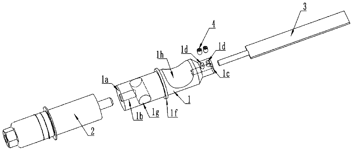
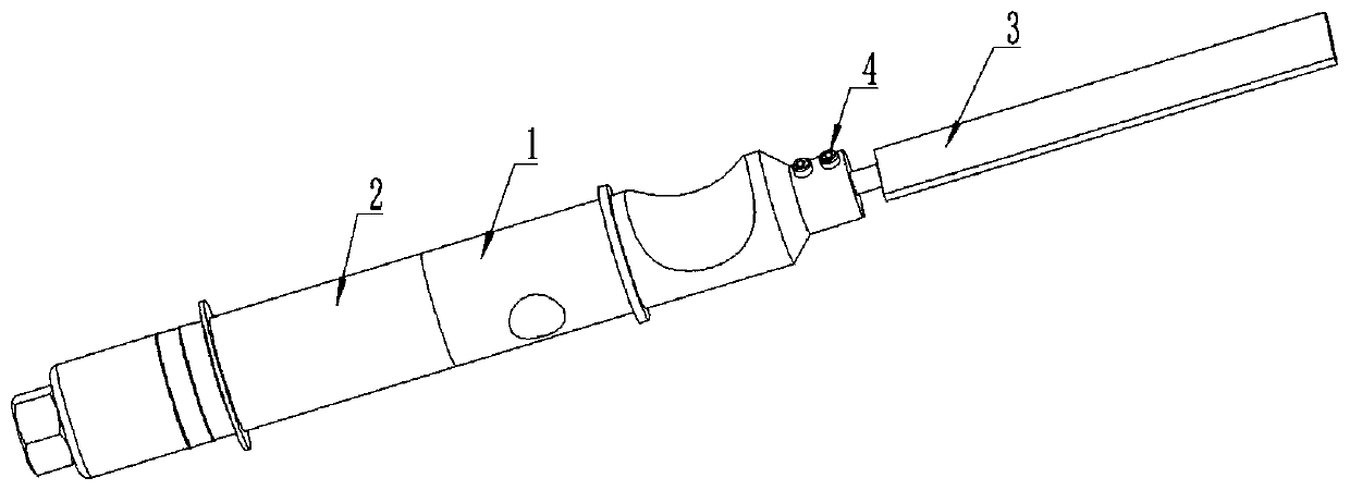
[0040] This embodiment provides an ultrasonic filing device realized by adopting longitudinal vibration and bending vibration ultrasonic horn, such as figure 2 As shown, it includes a horn 1, a longitudinal vibration excitation device 2, and a bending vibration tool 3.
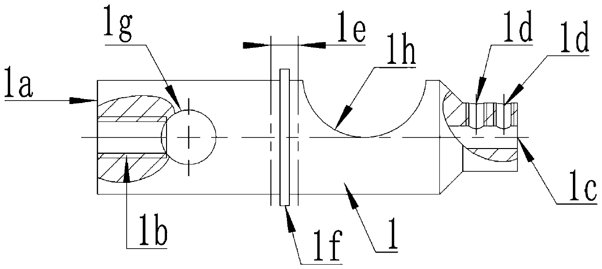
[0041] Such as figure 1 As shown, the front end of the horn 1 is provided with a longitudinal vibration input end 1a, and the longitudinal vibration input end 1a is provided with a connecting thread hole 1b, through which the longitudinal vibration input end 1a is connected to the longitudinal vibration excitation device 2. Preferably, the longitudinal vibration excitation device 2 is a piezoelectric ultrasonic transducer working in a longitudinal vibration mode.
[0042] The rear end of the horn 1 is provided with a bending vibration output end 1c, and the bending vibration output end 1c is provided with a tool clamping mechanism, and the bending vibration output end 1c is connected and fixed to the bending...
Embodiment 2
[0050]This embodiment provides an ultrasonic cutting device realized by adopting longitudinal vibration and bending vibration ultrasonic horn, such as Figure 5 As shown, the structure of this embodiment is generally the same as that of Embodiment 2, the difference is that the tool fixing and clamping mechanism of this embodiment is composed of an ER collet 5 and an ER nut 6 .
[0051] Specifically, the bending vibration tool 3 is assembled in the clamping hole of the ER collet 5, the ER collet 5 is assembled in the taper hole of the bending vibration output end 1c of the horn 1, and the ER nut 6 is screwed on the horn 1 On the bending vibration output end 1c of the horn 1, the ER nut 6 fixedly connects the bending vibration tool 3 to the bending vibration output end 1c of the horn 1 through the ER chuck 5 .
[0052] In this embodiment, the bending vibration tool 3 is a cutting tool working in a bending vibration mode.
[0053] The piezoelectric ultrasonic transducer connecte...
Embodiment 3
[0055] This embodiment provides an ultrasonic cutting device realized by adopting the longitudinal vibration bending ultrasonic horn, such as Figure 8 As shown, it includes a horn 1, a longitudinal vibration excitation device 2, and a bending vibration tool 3.
[0056] Such as Figure 7 As shown, the front end of the horn 1 is provided with a longitudinal vibration input end 1a, and the longitudinal vibration input end 1a is provided with a connecting thread hole 1b, through which the longitudinal vibration input end 1a is connected to the longitudinal vibration excitation device 2. Preferably, the longitudinal vibration excitation device 2 is a piezoelectric ultrasonic transducer working in a longitudinal vibration mode.
[0057] The rear end of the horn 1 is provided with a bending vibration output end 1c, and the bending vibration output end 1c is provided with a tool clamping mechanism, and the bending vibration output end 1c is connected and fixed to the bending vibrati...
PUM
 Abstract
Description
Claims
Application Information
 - Generate Ideas
- Intellectual Property
- Life Sciences
- Materials
- Tech Scout
- Unparalleled Data Quality
- Higher Quality Content
- 60% Fewer Hallucinations
Browse by: Latest US Patents, China's latest patents, Technical Efficacy Thesaurus, Application Domain, Technology Topic, Popular Technical Reports.
© 2025 PatSnap. All rights reserved.Legal|Privacy policy|Modern Slavery Act Transparency Statement|Sitemap|About US| Contact US: help@patsnap.com