Utility vehicle tyres

A technology for multi-purpose vehicles and tires, applied in vehicle parts, tire parts, tire treads/tread patterns, etc., can solve problems such as damage to groove walls and stone-discharging structures, prevent stone blockage, and improve stone-discharging effect of effect

Active Publication Date: 2020-06-12
CONTINENTAL REIFEN DEUTSCHLAND GMBH
View PDF8 Cites 2 Cited by
  • Summary
  • Abstract
  • Description
  • Claims
  • Application Information

AI Technical Summary

Problems solved by technology

As a result, stones jammed in the grooves can cause undesired damage to the groove walls and stone discharge structure

Method used


Image

  • Utility vehicle tyres
  • Utility vehicle tyres
  • Utility vehicle tyres

Examples


Embodiment Construction

[0035] Utility vehicle tires designed according to the invention are tires of radial design, in particular tires for construction site vehicles, trucks or buses.

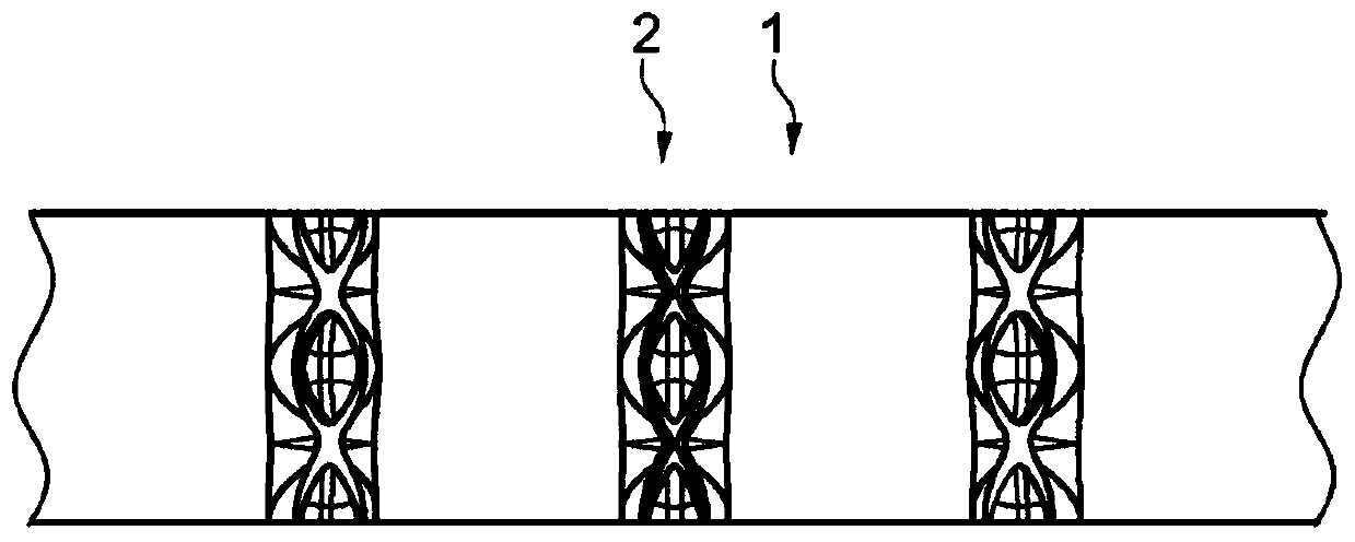
[0036] figure 1 The shown central circumferential section of the tread has a tread face 1 encircling in the circumferential direction a strip or block, shown schematically in simplified form and realized in particular in a known manner. Adjacent tread faces 1 in the axial direction are separated by respective circumferential grooves 2 extending linearly in plan view.

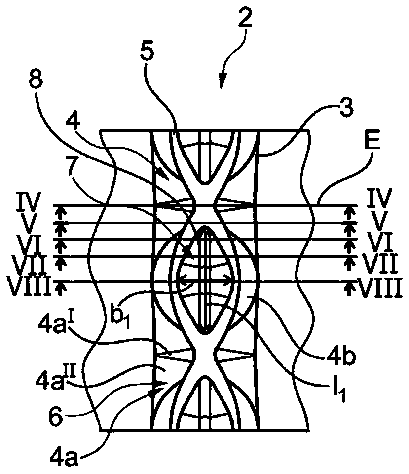
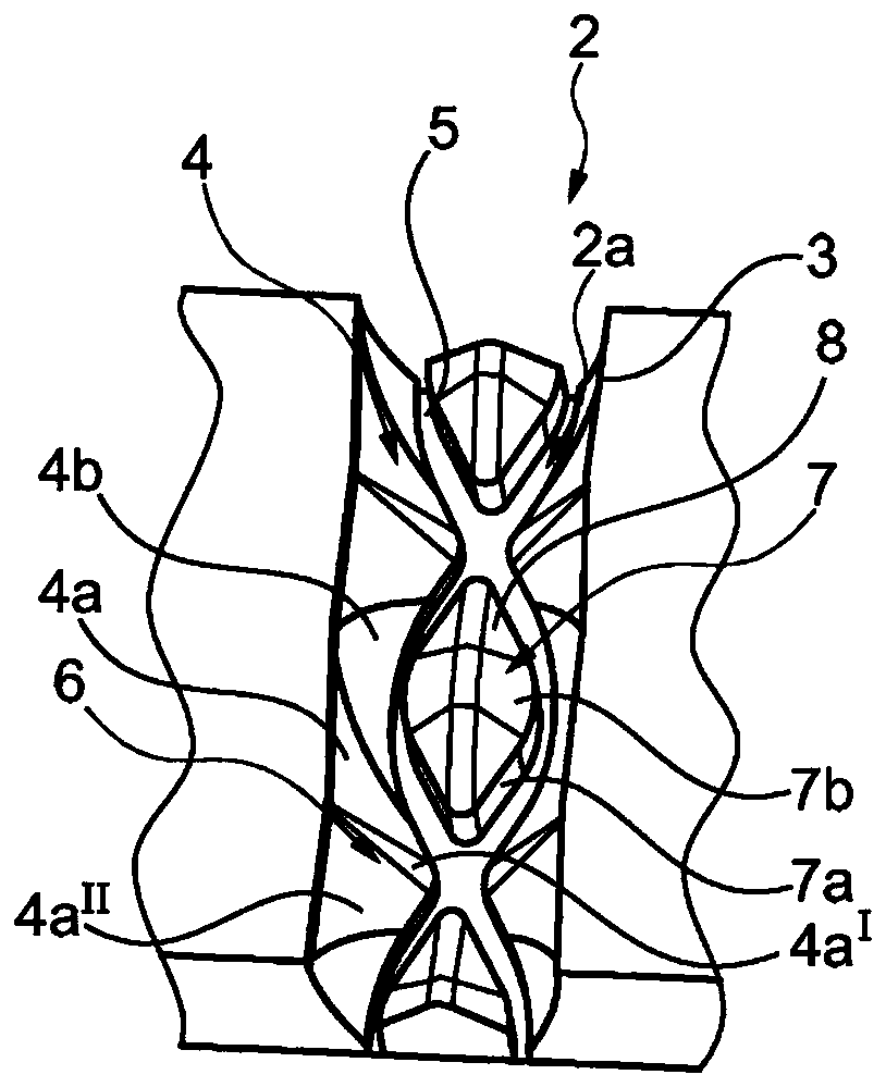
[0037] In the exemplary embodiment shown, the circumferential grooves 2 are designed in a corresponding manner. The following will refer to Figure 2 to Figure 8 The configuration of the circumferential groove 2 will be described with reference to the circumferential groove 2 shown in FIG.

[0038] Such as figure 2 and image 3As shown, a circumferential sipe 2 at the periphery of the tread is delimited by two sipe edges 3 which extend substanti...


PUM

PropertyMeasurementUnit
Extension lengthaaaaaaaaaa

Abstract

The invention relates to a utility vehicle tyre having a tread with at least one peripheral groove (2, 2', 2'') with a groove base (5) and groove walls (4, 4'). Base elevations (7, 7', 7'') with a height (h1, h3) of 25% to 60% of the profile depth (T1) and a greater extent in the peripheral direction than in the axial direction are formed on the groove base (5) in a manner distributed over the periphery and acting centrally as stone ejectors, said base elevations (7, 7', 7'') either contacting the groove walls (4, 4') or having distances (a) of up to 4.0 mm therefrom in the axial direction andbeing delimited in the radial direction by a cover face (8, 8', 8'') having a peripheral face edge. The groove walls (4, 4'), between the base elevations (7, 7', 7''), have wall portions (4a, 4'a) that converge towards one another. The cover face (8, 8', 8'') of the base elevations (7, 7', 7'') slopes away uniformly towards the face edge, the groove walls (4, 4') laterally of the base elevations(7, 7', 7'') having wall portions (4b, 4'b) that are curved convexly towards one another in plan view, and the face edge of the cover face (8, 8', 8'') following the course of the wall portions (4b, 4'b) that are curved convexly towards one another in such a way that the width of the base elevations (7, 7', 7'') decreases towards their ends disposed in the peripheral direction.

Description

technical field [0001] The invention relates to a utility vehicle tire, the tread of which has at least one circumferential groove with a groove base and a groove wall, wherein the elevations of the base are distributed over the circumference Formed on the groove base in a way and centrally used as a stone-removing structure, and the height of these base protrusions is 25% to 60% of the depth of the pattern, and the extension in the circumferential direction is greater than that in the axial direction By extension, the bases protrude in the axial direction in contact with the groove walls or at a distance of up to 4.0 mm from the groove walls, and are bounded in the radial direction by a top surface with a surrounding surface edge, wherein the The groove walls between the base elevations have wall segments that converge towards each other. Background technique [0002] A utility vehicle tire of the type described is known, for example, from JP S6 325 107 A . The tread of t...

Claims


Application Information

Patent Timeline
IPC IPC(8): B60C11/04B60C11/13B60C11/03
CPCB60C11/042B60C11/047B60C2011/0341B60C11/045B60C2011/1361B60C11/1315B60C2011/1338B60C11/0309
Inventor 安德烈·卢茨弗洛里安·克里斯滕
Owner CONTINENTAL REIFEN DEUTSCHLAND GMBH
Why Eureka
Try Eureka