Thin Film Transistor Driver Circuit

A technology of thin film transistors and driving circuits, which is applied in the field of thin film transistor driving circuits, can solve the problems of affecting the current range, limiting the maximum driving capacity of VGL, and increasing costs, so as to ensure the current capacity, reduce the large current, and solve the surge current. Effect

Active Publication Date: 2021-12-28
TCL CHINA STAR OPTOELECTRONICS TECH CO LTD
View PDF4 Cites 0 Cited by
  • Summary
  • Abstract
  • Description
  • Claims
  • Application Information

AI Technical Summary

Problems solved by technology

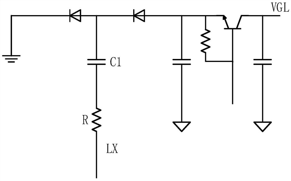
However, the current limit of this resistor R has always existed. After the current turns to normal, it will limit the maximum driving capability of VGL and affect the current range that this architecture can use. As a result, some models have to use Buck-Boost to generate VGL. increase the cost

Method used


Image

  • Thin Film Transistor Driver Circuit
  • Thin Film Transistor Driver Circuit

Examples


Embodiment Construction

[0020] The technical solutions in the embodiments of the present application will be clearly and completely described below in conjunction with the drawings in the embodiments of the present application. Apparently, the described embodiments are only some of the embodiments of this application, not all of them. Based on the embodiments in this application, all other embodiments obtained by those skilled in the art without making creative efforts belong to the scope of protection of this application.

[0021] In the description of the present application, it should be understood that the terms "center", "longitudinal", "transverse", "length", "width", "thickness", "upper", "lower", "front", " Orientation indicated by rear, left, right, vertical, horizontal, top, bottom, inside, outside, clockwise, counterclockwise, etc. The positional relationship is based on the orientation or positional relationship shown in the drawings, which is only for the convenience of describing the a...


PUM


Abstract

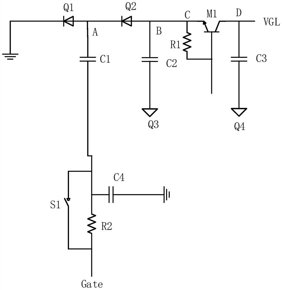
The invention discloses a thin film transistor drive circuit, comprising: a drive circuit including at least one resistor, at least one switch tube, at least three capacitors and at least four diodes, the drive circuit is used to receive an LX signal and convert the LX The signal is converted into a VGL signal; the current protection circuit is connected to the drive circuit at the node, and is used to eliminate the surge current at the beginning of the drive circuit, and the current protection circuit includes N resistors, N capacitors and N switches, N is a positive integer greater than or equal to 1. The thin film transistor driving circuit disclosed by the invention can not only solve the surge current at the beginning of the buck circuit, but also reduce the large current caused by VGL synchronously, and also ensure the current capacity of the VGL in the subsequent thin film transistor driving circuit.

Description

technical field [0001] The present application relates to the technical field of electronic circuits, in particular to a thin film transistor drive circuit. Background technique [0002] Liquid Crystal Display (LCD) is one of the most widely used flat-panel displays in the market. Liquid Crystal Displays require multiple operating voltages during their operation. These operating voltages are usually obtained by transforming the input voltage by the power management module of the drive circuit . The Boost circuit and the Buck circuit are the two most basic circuits in the power management module. The Boost circuit can boost the input voltage Vin to obtain the analog power supply voltage AVDD, and the Buck circuit can perform step-down processing on the input voltage Vin to obtain a digital power supply voltage. Supply voltage DVDD. [0003] Such as figure 1 As shown, in the current control of LCD thin film transistor panel drive, the LX signal of BuckDVDD is mostly used as...

Claims


Application Information

Patent Timeline
Patent Type & Authority Patents(China)
IPC IPC(8): H02M1/32H02M1/36H02H9/00H02H9/02
CPCH02M1/32H02M1/36H02H9/005H02H9/02
Inventor 张先明
Owner TCL CHINA STAR OPTOELECTRONICS TECH CO LTD
Why Eureka
Try Eureka