
Machining error detection method and device and machining method

A technology for processing errors and detection methods, applied in image data processing, instruments, calculations, etc., can solve the problems of inaccurate results, deformation, differences, etc., and achieve the effect of improving accuracy

Pending Publication Date: 2020-06-12
WUHAN UNIV OF SCI & TECH
View PDF5 Cites 0 Cited by
  • Summary
  • Abstract
  • Description
  • Claims
  • Application Information

AI Technical Summary

Problems solved by technology

[0002] At present, the detection of the geometric accuracy of large-scale CNC machine tools in China usually uses offline detection to measure the static accuracy, but the machining accuracy is directly related to the actual working conditions of the machine tool, so the result of offline detection is not accurate
Especially for thin-walled workpieces, because of the vibration and deformation under the action of cutting force, the measurement results during dynamic processing are quite different from the static off-line measurement results.

Method used


Image

  • Machining error detection method and device and machining method
  • Machining error detection method and device and machining method
  • Machining error detection method and device and machining method

Examples


Embodiment Construction

[0017] In order to understand the above-mentioned purpose, features and advantages of the present invention more clearly, the present invention will be further described in detail below in conjunction with the accompanying drawings and specific embodiments. It should be noted that, in the case of no conflict, the embodiments of the present invention, that is, the features in the embodiments may be combined with each other.

[0018] In the following description, many specific details are set forth in order to fully understand the present invention. However, the present invention can also be implemented in other ways different from those described here. Therefore, the protection scope of the present invention is not limited by the specific details disclosed below. EXAMPLE LIMITATIONS.

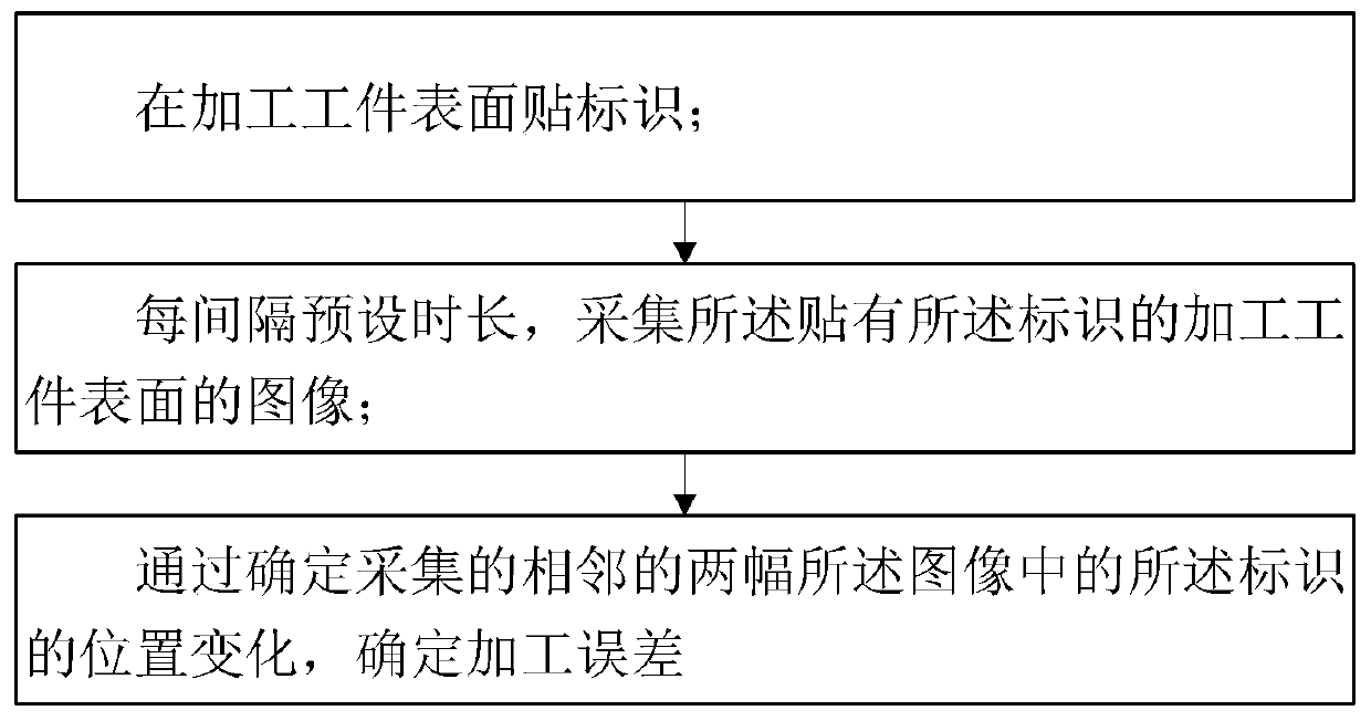
[0019] figure 1 A flow chart of a processing error detection method, a processing method and a processing device provided according to an embodiment of the present invention is shown.

[0020] ...


PUM


Abstract

The invention discloses a machining error detection method. The method comprises the following steps that a mark is pasted on the surface of a machined workpiece; continuously collecting images of thesurface of the machined workpiece pasted with the identifier at preset time intervals; and determining a processing error by determining the position change of the identifier in the two adjacent acquired images. According to the method, the mark is pasted on the surface of the machined workpiece, the image is collected, the machining error is determined by recognizing the position change of the mark in the image, and the machining error is dynamically detected online during machining, so that the measurement of the machining error is more consistent with the actual working condition, and themeasurement accuracy is improved. The invention further discloses a machining method and a machining error detection device.

Description

technical field [0001] The invention relates to the field of processing technology, in particular to a processing error detection method, device and processing method. Background technique [0002] At present, the detection of the geometric accuracy of large-scale CNC machine tools in China usually uses offline detection to measure the static accuracy, but the machining accuracy is directly related to the actual working conditions of the machine tool, so the results of offline detection are not accurate. Especially for thin-walled workpieces, because of the vibration and deformation under the action of cutting force, the measurement results during dynamic processing are quite different from the static off-line measurement results. Contents of the invention [0003] Based on the above problems, the present invention proposes a processing error detection method, device and processing method. [0004] In view of this, the present invention proposes a kind of processing error...

Claims


Application Information

Patent Timeline
Patent Type & Authority Applications(China)
IPC IPC(8): G06T7/00G06T7/13
CPCG06T7/001G06T7/13G06T2207/30164
Inventor 肖骏松赵刚颜鹏程
Owner WUHAN UNIV OF SCI & TECH
Learn More