
Fluorescence detection optical system

An optical system and fluorescence detection technology, which is applied in the field of fluorescence detection, can solve the problems of complex and huge optical path structure, difficulty in aligning the sample position with the detection channel and the focal point of the optical path, and achieve simple optical path structure, miniaturization and modularization, and optical path Reasonable and compact layout

Active Publication Date: 2020-06-12
SHENGZHEN CHINA GENE TECH COMPANY
View PDF9 Cites 3 Cited by
  • Summary
  • Abstract
  • Description
  • Claims
  • Application Information

AI Technical Summary

Problems solved by technology

[0003] However, the existing fluorescence detection optical system has a complex and huge optical path structure, and it is not easy to align the sample position with the corresponding detection channel and the focal point of the optical path

Method used


Image

  • Fluorescence detection optical system
  • Fluorescence detection optical system
  • Fluorescence detection optical system

Examples


Embodiment Construction

[0040] In order to make the technical problems solved by the present invention, the technical solutions adopted and the technical effects achieved clearer, the technical solutions of the embodiments of the present invention will be further described in detail below in conjunction with the accompanying drawings. Obviously, the described embodiments are only the technical solutions of the present invention. Some, but not all, embodiments. Based on the embodiments of the present invention, all other embodiments obtained by those skilled in the art without creative efforts fall within the protection scope of the present invention.

[0041] In the description of the present invention, it should be noted that the terms "center", "upper", "lower", "left", "right", "vertical", "horizontal", "inner", "outer" etc. The indicated orientation or positional relationship is based on the orientation or positional relationship shown in the drawings, and is only for the convenience of describin...


PUM


Abstract

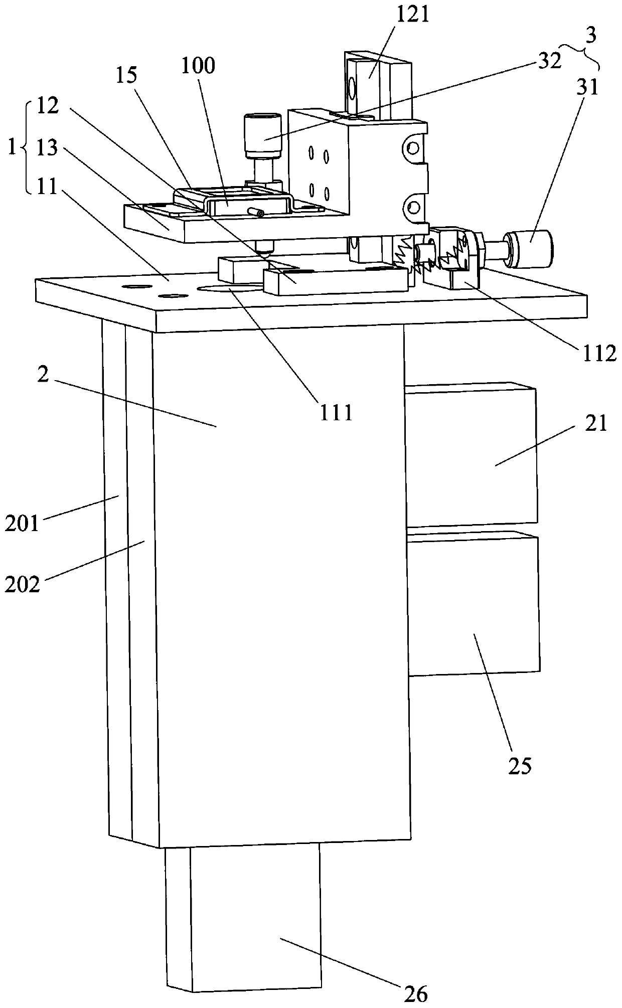
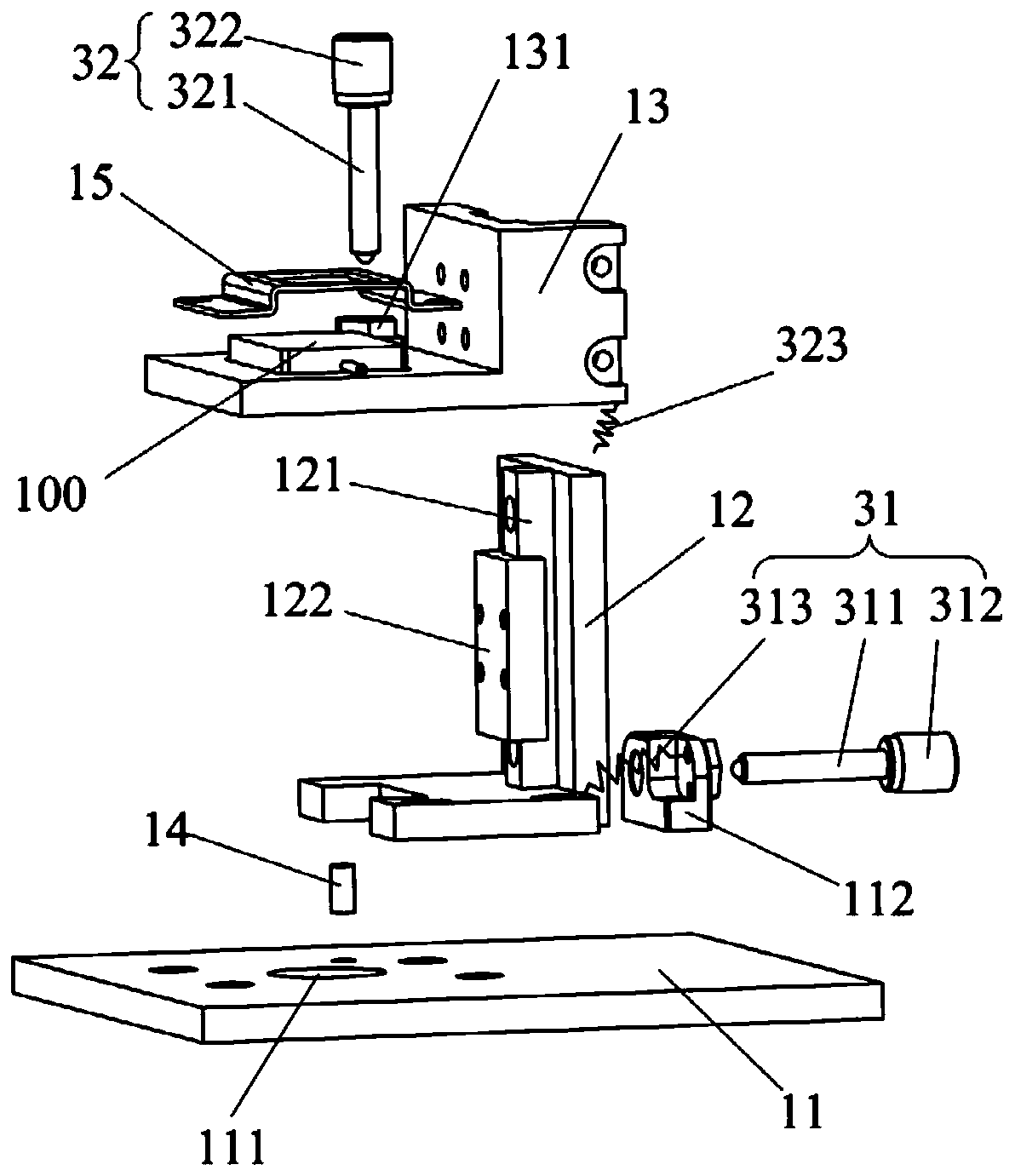
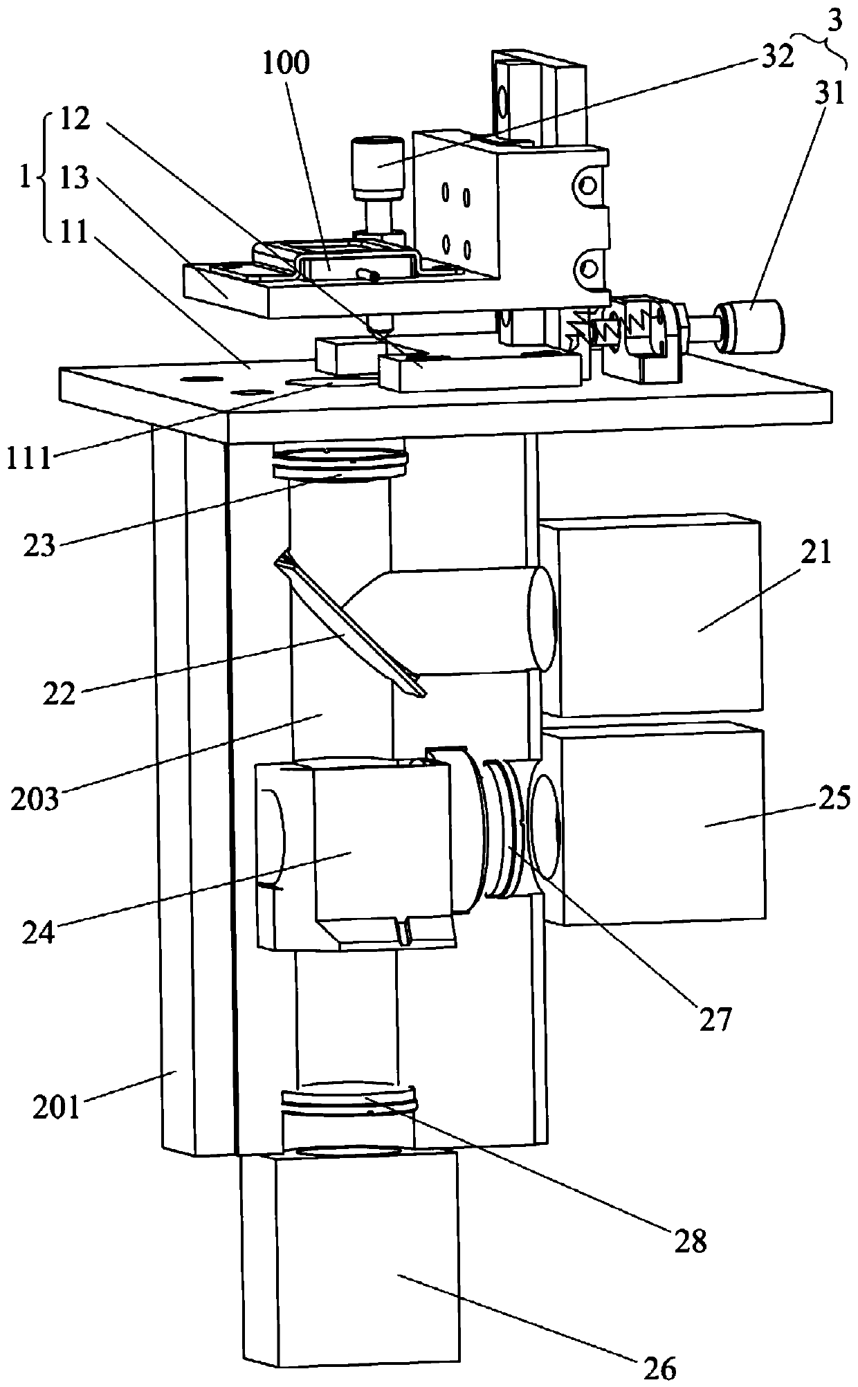
The invention relates to the field of fluorescence detection, and discloses a fluorescence detection optical system. The fluorescence detection optical system comprises an objective table, a light path module and an adjusting mechanism, the objective table is used for placing a sample to be detected, and the objective table is provided with a detection channel; the light path module is used for exciting and detecting a fluorescence signal of a to-be-detected sample, a detection light path is arranged in the light path module, and the detection light path is communicated with the detection channel; the adjusting mechanism comprises a first adjusting assembly and a second adjusting assembly, the first adjusting assembly is used for adjusting the to-be-detected sample to be aligned with the detection channel, and the second adjusting assembly is used for adjusting the to-be-detected sample to coincide with the focus point of the detection light path. The fluorescence detection optical system provided by the invention is simple, convenient and accurate in sample position calibration, simple in optical path structure, reasonable and compact in optical path layout, and easy to realize miniaturization and modularization.

Description

technical field [0001] The invention relates to the field of fluorescence detection, in particular to a fluorescence detection optical system. Background technique [0002] Biochip technology is to use micro-processing technology combined with related chemical synthesis technology to immobilize a large number of probe molecules on the carrier to make a biochip. The probe molecules are hybridized with the sample molecules labeled with tracers. The distribution and strength of the tracer signal can be used to obtain information such as the sequence and quantity of the target molecule. The detection of tracer signals is an important part of biochip technology, which determines the rapidity and accuracy of biochip technology. At present, fluorescent substances are commonly used as tracers. In the fluorescence detection method, the base carrying the fluorescent material is combined with the genetic material of the sample. When excited by the excitation light source, the fluoresc...

Claims


Application Information

Patent Timeline
Patent Type & Authority Applications(China)
IPC IPC(8): G01N21/64G01N21/01
CPCG01N21/6486G01N21/6428G01N21/01G01N2021/0112G01N2201/068
Inventor 彭旭
Owner SHENGZHEN CHINA GENE TECH COMPANY
Learn More