
Exhaust air temperature difference control system and control method utilizing air duct beams and walls and draught fan group

An air duct beam wall and control system technology, which is applied to the control input involving air characteristics, ventilation system, space heating and ventilation control input, etc. Large, can not meet the requirements of engineering application and other problems

Active Publication Date: 2020-06-12
中国人民解放军火箭军工程设计研究院
View PDF7 Cites 1 Cited by
  • Summary
  • Abstract
  • Description
  • Claims
  • Application Information

AI Technical Summary

Problems solved by technology

At present, there are multiple streams of exhaust air flowing into the air duct at different positions. The air temperature in the air duct fluctuates widely, and the difference between the exhaust air temperature and the outdoor temperature is large and uneven, which cannot meet the special application requirements of the project.
[0003] Although there have been related improvements in the study of exhaust air temperature difference, such as the Chinese invention patent application CN201910009991.2 (a control method and system for differential operation of compressors), this technology still focuses on energy-saving considerations in civil or commercial fields, which belongs to The research on the operating frequency and power consumption control of air-conditioning compressors does not involve the relationship between indoor and outdoor exhaust air temperature difference, uniformity of temperature field and concealment

Method used


Image

  • Exhaust air temperature difference control system and control method utilizing air duct beams and walls and draught fan group
  • Exhaust air temperature difference control system and control method utilizing air duct beams and walls and draught fan group
  • Exhaust air temperature difference control system and control method utilizing air duct beams and walls and draught fan group

Examples


Embodiment Construction

[0054] In order to make the purpose, technical solutions and advantages of the embodiments of the present invention more clear, the embodiments of the present invention will be further described in detail below in conjunction with the embodiments and the accompanying drawings. Here, the exemplary embodiments and descriptions of the present invention are used to explain the present invention, but not to limit the present invention.

[0055]In describing the present invention, it should be understood that the terms "upper", "lower", "front", "rear", "left", "right", "top", "bottom", "inner", " "Outside" and other indication orientations or positional relationships are based on the orientations or positional relationships shown in the drawings, which are only for the convenience of describing the present invention and simplifying the description, rather than indicating or implying that the referred device, component or structure must have a specific orientation, Construction or o...


PUM


Abstract

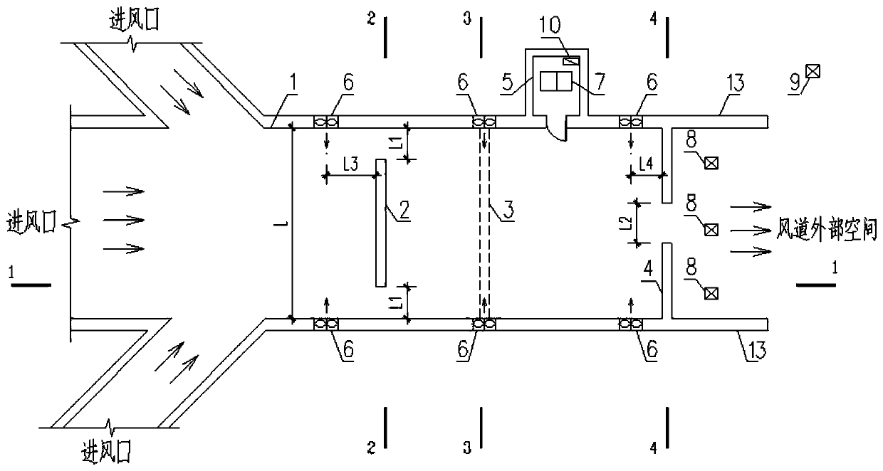
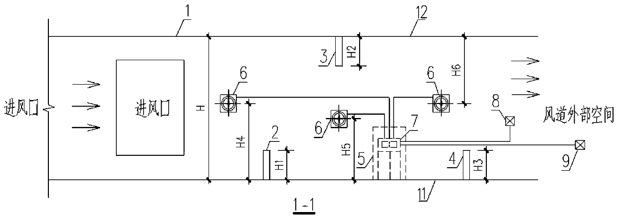
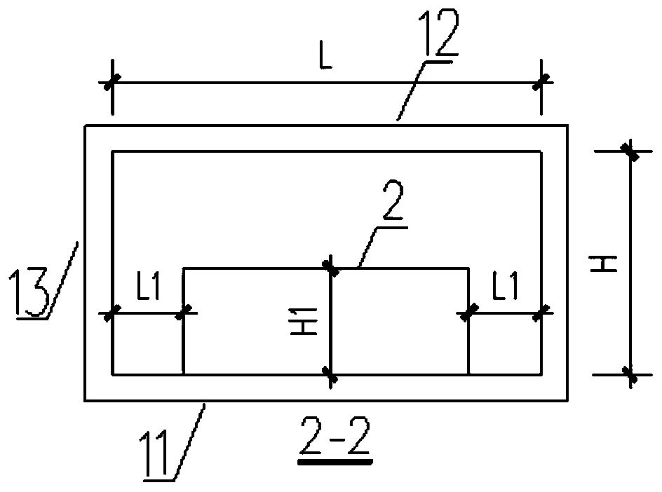
The invention provides an exhaust air temperature difference control system and control method utilizing air duct beams and walls and a draught fan group. The control system comprises an air disturbance structure and an air mixing system. The air disturbance structure is arranged in an air duct and comprises the first mixing walls, the mixing beams and the second mixing walls which are sequentially arranged from an air inlet to an air outlet of the air duct. The air disturbance structure is used for conducting uniform disturbance on multiple strands of air converged in the air duct so that theair temperature field of the air outlet of the air duct can be uniform. The air mixing system comprises the mixing variable-frequency draught fan group, a controller, an internal sensor and externalsensors. The air mixing system is used for mixing the air converged into the air duct so that the temperature difference of the air temperature of the air outlet of the air duct and the temperature ofthe external space can be kept within the temperature difference threshold range. According to the air duct exhaust air temperature difference control technology utilizing the beams and the walls inthe air duct and the draught fan group, by combining two measures, the aims of making the exhaust air temperature of the air duct uniform and controlling the temperature difference of the exhaust airtemperature and the external environment temperature within the predetermined limitation are achieved.

Description

technical field [0001] The invention belongs to the technical field of exhaust air temperature and outdoor temperature difference control for special projects, and in particular relates to an exhaust air temperature difference control system and control method using air duct beam walls and fan groups. Background technique [0002] For special projects, the exhaust air needs to be concealed. For example, the temperature field of the exhaust air should be uniform, and the temperature difference with the environment should be controlled within the specified range, so that it will not be easily detected by infrared or thermal induction. At present, there are multiple streams of exhaust air flowing into the air duct at different positions. The temperature fluctuation range of the air in the air duct is large, and the difference between the exhaust air temperature and the outdoor temperature is large and uneven, which cannot meet the special application requirements of the project....

Claims


Application Information

Patent Timeline
Patent Type & Authority Applications(China)
IPC IPC(8): F24F13/02F24F5/00F24F7/06F24F11/89F24F13/04F24F110/10
CPCF24F5/00F24F7/06F24F11/89F24F13/0245F24F13/04F24F2110/10
Inventor 苏辉李吉张金城方仲元涂江峰孙海石
Owner 中国人民解放军火箭军工程设计研究院
Learn More