Cross braiding machine for national costume decoration belt
A technology for knitting machines and garments, applied in knitting, textiles and paper making, etc., can solve the problems of large floor space, low speed of fork gears, and large shape of knitting machines, so as to increase production, increase operating speed, and reduce The effect of the number of teeth
- Summary
- Abstract
- Description
- Claims
- Application Information
AI Technical Summary
Problems solved by technology
Method used
Image
Examples
Embodiment 1
[0044] Embodiment 1: the braiding machine includes: a braiding assembly, a frame 1-4 and a take-up device 1-1; the braiding assembly and the take-up device 1-1 are all installed on the frame 1-4, and the take-up The device 1-1 is installed on the top of the braiding machine assembly through a pillar; the braiding assembly includes: a lower plate 1-3, an upper plate 1-7, a motor 1-6, a spindle 1-2, and a pull-type shift fork device, guide rail and pull cross guide rail; the upper end of the lower plate 1-3 is connected with the upper plate 1-7, and the pull cross type shifting device is installed on the upper plate, and the guide rail and the pull cross guide rail are arranged, and the guide rail and the pull cross guide rail Smooth transition, the pull-cross fork device cooperates with the pull-cross guide rail to drive the spindle for pull-cross weaving.
[0045] The pull cross type shifting fork device includes: left guide rail single spindle unit group 1-8, right guide rail...
Embodiment 2
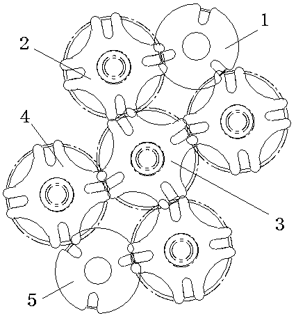
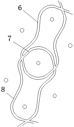
[0054] Example 2: Figure 13 It is the structure diagram of the state structure diagram of the pull-cross type twin-spindle braiding in the braiding machine of the present invention. Figure 14 yes Figure 13 The running guide rail structure diagram.
[0055] The two-spindle knitting machine of the pull-cross type includes: two sets of pull-type knitting systems, extension gear dials 13, and extension guide rails 14; the two sets of pull-type knitting systems are meshed by the extension gear dials 13; There is an extension guide rail 14 between the head ends of the guide rails of the pull-cross braiding system, and the extension guide rails 14 connect the guide rails of the two sets of pull-cross braiding systems in a smooth transition.
[0056] Among them, one group of front rotary gear dials 1 is a six-fork dial gear, and the rear rotary gear dial 5 is a four-fork dial gear; the other group of front rotary gear dials 1 and rear rotary gear dials 5 are both Four-fork dial ...
Embodiment 3
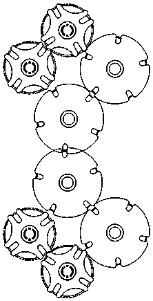
[0058] Example 3: Figure 15 It is a structural diagram of the state of the braiding single-spindle knitting machine of the present invention. Figure 16 yes Figure 15 The running guide rail structure diagram.
[0059] The pull-type single-spindle knitting machine includes: two sets of pull-type braiding systems, extended gear dials 13, and extended guide rails 14; There is an extension guide rail 14 between the head ends of the guide rails of the pull-cross braiding system, and the extension guide rails 14 connect the guide rails of the two sets of pull-cross braiding systems in a smooth transition.
[0060] Wherein, the front rotary gear dial 1 and the rear rotary gear dial 5 of the two groups are all four-fork dial gears.
[0061] Others are the same as in Example 1.
PUM
 Abstract
Description
Claims
Application Information
 - R&D Engineer
- R&D Manager
- IP Professional
- Industry Leading Data Capabilities
- Powerful AI technology
- Patent DNA Extraction
Browse by: Latest US Patents, China's latest patents, Technical Efficacy Thesaurus, Application Domain, Technology Topic, Popular Technical Reports.
© 2024 PatSnap. All rights reserved.Legal|Privacy policy|Modern Slavery Act Transparency Statement|Sitemap|About US| Contact US: help@patsnap.com


